
| Forcefield Based Simulations |
Molecular dynamics solves the classical equations of motion for a system of N atoms interacting according to a potential energy forcefield as described in Forcefields. Dynamics simulations are useful in studies of the time evolution of a variety of systems at nonzero temperatures, for example, biological molecules, polymers, or catalytic materials, in a variety of states, for example, crystals, aqueous solutions, or in the gas phase.
Related information
Forcefields and Preparing the Energy Expression and the Model focus on the representation of the potential energy surface and the useful ways that it can be biased through the addition of restraints and constraints, as well as other information on preparing the model system for calculations.
Use of simulation engines for calculating normal modes is found under Vibrational calculation.
For specific information on setting up and running dynamics calculations with the various MSI simulation engines, please see the relevant documentation (see Available documentation).
Some uses of dynamics calculations
The major applications of molecular dynamics are:
Other approaches to simulating molecular motion and generating conformational searches exist.
This section includes:![]()
Integration algorithms
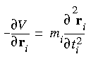
At its simplest, molecular dynamics solves Newton's familiar equation of motion:
Eq. 83
![]() where Fi is the force, mi is the mass, and ai is the acceleration of atom i.
where Fi is the force, mi is the mass, and ai is the acceleration of atom i.
Eq. 84
 What is a trajectory?
Notice that classical equations of motion are deterministic. That is, once the initial coordinates and velocities are known, the coordinates and velocities at a later time can be determined. The coordinates and velocities for a complete dynamics run are called the trajectory. (However, trajectories are sensitive to initial conditions, so the same simulation run with a different simulation engine or on a different computer does not produce an identical trajectory.)
A standard method of solving an ordinary differential equation such as Eq. 84 numerically is the finite-difference method. The general idea is as follows. Given the initial coordinates and velocities and other dynamic information at time t, the positions and velocities at time t +  t are calculated. The timestep t depends on the integration method as well as the system itself.
Defined initial coordinates and random initial velocities
Although the initial coordinates are determined in the input file or from a previous operation such as minimization, the initial velocities are randomly generated at the beginning of a dynamics run, according to the desired temperature. Therefore, dynamics runs cannot be repeated exactly, except for forcefield engines (CHARM standalone, Discover) that allow you to set the random number seed to the value that was used in a previous run.
Criteria of good integrators in molecular dynamics
Molecular dynamics is usually applied to a large model. Energy evaluation is time consuming and the memory requirement is large. To generate the correct statistical ensembles, energy conservation is also important.
| integrator | simulation engine | ||
|---|---|---|---|
| CHARMm | Discover | OFF | |
|
Verlet leapfrog
|

|
1
|
|
|
Verlet velocity
|
|
2
|
|
|
ABM4
|
|
2
|
|
|
Runge-Kutta-4
|
|
2
|
|
| 1
FDiscover only, not in CDiscover. 2 CDiscover only, not in FDiscover.
|
To specify the dynamics integrator:
Variants of the Verlet (1967) algorithm of integrating the equations of motion (Eq. 84) are perhaps the most widely used method in molecular dynamics. The advantages of Verlet integrators is that these methods require only one energy evaluation per step, require only modest memory, and also allow a relatively large timestep to be used.
The Verlet leapfrog algorithm is as follows:
t/2), and a(t), which are (respectively) the position, velocity, and acceleration at times t, t -t/2, and t, compute:
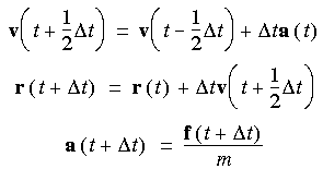
t) is evaluated from -dV/dr at r (t + t).
The Verlet leapfrog method has one major disadvantage: the positions and velocities calculated are half a timestep out of synchrony.
Verlet velocity integrator
The Verlet velocity algorithm overcomes the out-of-synchrony shortcoming of the Verlet leapfrog method. The Verlet velocity algorithm is as follows:
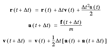
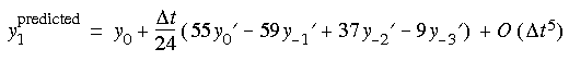
This method requires two energy evaluations per step and has to make use of the results of the previous three steps. It is thus not self starting--the first three steps are generated by the Runge-Kutta method. More memory has to be used, because previous information has to be stored.
ABM4's algorithm
t, t - t, t - 2t, and t - 3t.
Runge-Kutta-4 stands for the fourth-order Runge-Kutta method, which is one of the oldest numerical methods for solving ordinary differential equations. The method is self starting but requires four energy evaluations per step.
A key parameter in the integration algorithms is the integration timestep ![]()
The choice of timestept. To make the best use of the computer time, a large timestep should be used. However, too large a timestep causes instability and inaccuracy in the integration process.
The timestep used depends on the model as well as the integrators. The main limitation imposed by the model is the highest-frequency motion that must be considered. A vibrational period must be split into at least 8-10 segments for models to satisfy the Verlet assumption that the velocities and accelerations are constant over the timestep used.
If you are studying simple model liquids or solids and are not interested in internal modes, much longer timesteps may be used, e.g., up to 20 fs. A timestep of about 5 fs should be adequate for ionic material models.
The timestep must also be appropriate to the integrator. For the ABM4 method, the timestep should be about half that needed for the Verlet algorithm. The Runge-Kutta-4 method seems to require a much smaller timestep than the other methods.
To specify the length of the timestep:
Two examples illustrate how the timestep, temperature, and integration algorithm affect the results. The first example is a simulation of the collision of two hydrogen atoms travelling towards each other. The second is an examination of energy conservation in a simple harmonic oscillator when different integrators and timesteps are used.
Timestep slightly too large
To illustrate this, consider the collision of two atoms. Figure 26 plots the true potential energy of the van der Waals potential between two hydrogens along with the energy integrated numerically from the forces. The time step used is 1 fs at a temperature of 300 K. The temperature is set by assigning an initial velocity of 1500 m s-1 (0.015Å fs-1) to one of the hydrogens along the vector connecting them. This velocity is the most probable velocity of a hydrogen atom at 300 K.
|
As the two atoms approach each other, the integration agrees well with the analytic curve. However, after the atoms collide, the integrated energy is significantly higher than the true energy. This behavior is due to the atom moving too quickly through a rapidly changing energy function. When the atoms are far apart, the energy change is smallest and therefore, the forces are smallest and most linear. As the atoms approach, they speed up and take larger and larger steps, until they reach their highest velocity at the energy minimum. Unfortunately, this is precisely where the forces start changing the fastest. Thus, when the atoms should be taking large steps (far apart), they are taking the smallest steps, and when they should take small steps (near the minimum), they take the largest steps. The consequence is that the particles "step through" the energy barrier momentarily. Of course, once a new force is calculated at the extrapolated coordinate, the trajectory is rapidly corrected. However, it is too late for the energy integral--some energy has been gained.
Figure 27 shows the same curve as Figure 26, but with timesteps of 0.33 and 0.10 fs. Both give better results than 1.0 fs, but it is not clear whether the extra time required to calculate the smaller timesteps is worthwhile.
|
A very large timestep leads to artifactual behavior
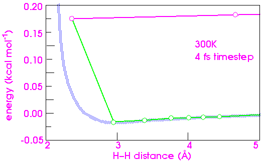
The consequences of too large a time step are much more dramatic. Doubling the time step from 1 to 2 fs results in an unusual artifact for the hydrogen system (Figure 28). In this case, the integration error affects not only the potential energy, but the kinetic energy as well. Momentum is removed, so that the hydrogens no longer have the velocity needed to escape after the collision. The atoms are trapped forever (barring an inverse error that could impart momentum). The atoms now vibrate back and forth (only 2 cycles are plotted in Figure 28), and each cycle incurs an additional integration error.
|
An even higher timestep can cause the system to explode
Increasing the time step another factor of 2 to 4 fs (Figure 29) finally causes the system to "blow up". The timestep is so long that the atoms deeply interpenetrate each other's steeply repulsive wall between steps. The resulting force is now so large that the atoms fly off at a speed of about 1 Å fs-1 (or 105 m s-1). An equivalent temperature would be hundreds of thousands of degrees.
|
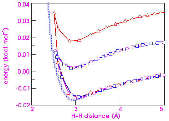
To complete the analysis of integration errors, it is instructive to compare the effects of increasing kinetic energy on the stability of the numerical integration. Figure 30 shows that there is essentially no difference in the error between 300 and 1200 K. Going as high as 30,000 K merely almost doubles the error, indicating that dynamics simulations are not as sensitive to the temperature as to the timestep.
|
Example 2--Energy conservation of a harmonic oscillator
Verlet velocity vs. ABM4
To test the conservation of energy in a simulation, 10 ps of molecular dynamics was performed on a harmonic oscillator having an equilibrium length of 0.75 Å and period of 7.5 fs. As can be seen in Table 18, the Verlet velocity method can use a larger timestep than the ABM4 method. Although the Verlet algorithm starts to show instability at 1 fs, ABM4 starts to fail at 0.25 fs.
| integrator | timestep fs | final energy kcal mol-1 | average energy kcal mol-1 | standard deviation kcal mol-1 |
|---|---|---|---|---|
|
Verlet velocity
|
1.0
|
0.327
|
0.325
|
0.021
|
|
Verlet velocity
|
0.5
|
0.296
|
0.302
|
0.005
|
|
Verlet velocity
|
0.25
|
0.298
|
0.298
|
0.001
|
|
ABM4
|
0.25
|
0.693
|
0.467
|
0.114
|
|
ABM4
|
0.10
|
0.299
|
0.297
|
0.001
|
You can control the temperature and pressure
![]()
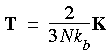
Statistical ensembles
Integrating Newton's equations of motion allows you to explore the constant-energy surface of a system. However, most natural phenomena occur under conditions where a system is exposed to external pressure and/or exchanges heat with the environment. Under these conditions, the total energy of the system is no longer conserved, and extended forms of molecular dynamics are required.
Several methods are available for controlling temperature and pressure. Depending on which state variables (the energy E, enthalpy H (i.e., E + PV), number of particles N, pressure P, stress S, temperature T, and volume V) are kept fixed, different statistical ensembles can be generated. A variety of structural, energetic, and dynamic properties can then be calculated from the averages or the fluctuations of these quantities over the ensemble generated.
Choosing the thermodynamic ensemble
To access the controls used for specifying the thermodynamic ensemble:
The constant-energy, constant-volume ensemble (NVE), also known as the microcanonical ensemble, is obtained by solving the standard Newton equation without any temperature and pressure control. Energy is conserved when this (adiabatic) ensemble is generated. However, because of rounding and truncation errors during the integration process, there is always a slight fluctuation or drift in energy.
t) are known at each timestep. Thus, the potential and kinetic energies at each timestep are also half a step out of synchrony. Although the difference between the kinetic energies half a timestep apart is small, this can also contribute to the fluctuation in the total energy.
True constant-energy conditions (i.e., without temperature contol) are not recommended for equilibration because, without the energy flow facilitated by temperature control, the desired temperature cannot be achieved.
The results can be used (Equilibrium thermodynamic properties) to calculate the thermodynamic response function (Ray 1988).
NVT ensemble
The constant-temperature, constant-volume ensemble (NVT), also referred to as the canonical ensemble, is obtained by controlling the thermodynamic temperature. Direct temperature scaling should be used only during the initialization stage (Stages and duration of dynamics simulations), since it does not produce a true canonical ensemble (it is not truly isothermal). Any of the other temperature-control methods available (How temperature is controlled) is used during the data collection phase.
This is the appropriate choice when conformational searches of models are carried out in vacuum without periodic boundary conditions. (Without periodic boundary conditions, volume, pressure, and density are not defined and constant-pressure dynamics cannot be carried out.)
NPT and NST ensembles
Periodic systems
The constant-temperature, constant-pressure ensemble (NPT) allows control over both the temperature and pressure. The unit cell vectors are allowed to change, and the pressure is adjusted by adjusting the volume (i.e., the size and also, in some programs, the shape of the unit cell). This method applies only to periodic systems.
Pressure can be controlled by the Berendsen, Andersen, or Parrinello-Rahman method (How pressure and stress are controlled). However, only the size, and not the shape, of the unit cell can be changed with the Berendsen and Anderson methods (Berendsen method of pressure control and Andersen method of pressure control).
Stress can be controlled by the Parrinello-Rahman method (Parrinello-Rahman method of pressure and stress control), since it allows both the cell volume and its shape to change.
Temperature can be controlled by any method available (How temperature is controlled) (except, of course, the temperature scaling method, since it is not truly isothermal).
NPT is the ensemble of choice when the correct pressure, volume, and densities are important in the simulation. This ensemble can also be used during equilibration to achieve the desired temperature and pressure before changing to the constant-volume or constant-energy ensemble when data collection starts.
The NST ensemble is particularly useful if you want to run a simulation at incremented tensile loads to study the stress-strain relationship in polymeric or metallic materials.
NPH and NSH ensembles
Periodic systems
The constant-pressure, constant-enthalpy ensemble (NPH, Andersen 1980, see also Andersen method of pressure control) is the analogue of constant-volume, constant-energy ensemble, where the size of the unit cell is allowed to vary. In the constant-pressure (or -stress), constant-enthalpy ensemble (NPH or NSH, Parrinello and Rahman 1981, see also Parrinello-Rahman method of pressure and stress control), both the size and shape of the unit cell are allowed to vary (meaning that external stress can be applied). These methods apply only to 3D periodic systems.
Enthalpy H, which is the sum of E and PV, is constant when the pressure is kept fixed without any temperature control. Although the temperature is not controlled during true (adiabatic) NPH or NSH dynamics, you might want to use these conditions during the equilibration phase (Stages and duration of dynamics simulations) of your simulation. For this purpose, Cerius2·Discover and Cerius2·Dynamics Simulation allow you to hold the temperature within specified tolerances by periodic scaling of the velocities.
The natural response functions (specific heat at constant pressure, thermal expansion, adiabatic compressibility, and adiabatic compliance tensor) are obtained (Equilibrium thermodynamic properties) from the proper statistical fluctuation expressions of kinetic energy, volume, and strain (Ray 1988).
Equilibrium thermodynamic properties
Precautions
Since the ensembles are artificial constructs, they produce averages that are consistent with one another when they represent the same state of the model. Nevertheless, the fluctuations vary in different ensembles. Some of the fluctuations are related to thermodynamic derivatives, such as the specific heat or the isothermal compressibility.
Caution
|
In practice, obtaining accurate fluctuations to calculate physical quantities is difficult, and this approach should be used with caution. |
The transformation and relation between different ensembles has been discussed in greater detail by Allen and Tildesley (1987).
One of the objectives of molecular dynamics is to obtain the equilibrium thermodynamic properties of a model. If a microscopic dynamic variable A takes on values A(t) along a trajectory, then the following time average:
Eq. 85
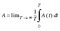 yields the thermodynamic value for the selected variable. This dynamic variable can be any function of the coordinates and momenta of the particles of the model.
Through time averaging, you can calculate the first-order properties of a system (such as the internal energy, kinetic energy, pressure, and virial). Similarly, using microscopic expressions in the form of fluctuations of these first-order properties, you can also calculate thermodynamic properties of a system. These include the specific heat, thermal expansion, and bulk modulus.
However, second-order properties such as specific heats, compressibilities, and elastic constants differ between ensembles. For example, the specific heat at constant pressure differs from the specific heat at constant volume.
This section includes:![]()
Temperature
Relation of temperature and velocity
Temperature is a state variable that specifies the thermodynamic state of the system and is also an important concept in dynamics simulations. This macroscopic quantity is related to the microscopic description of simulations through the kinetic energy, which is calculated from the atomic velocities.
Eq. 86
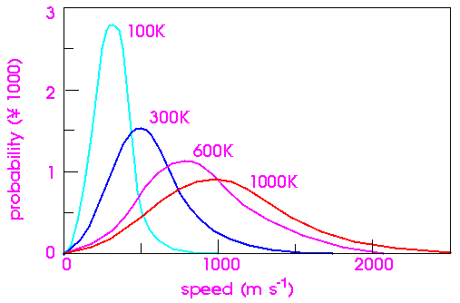
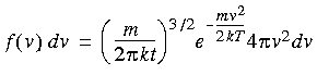 This well known formula expresses the probability f (v) that a molecule of mass m has a velocity of v when it is at temperature T. Figure 31 shows this distribution at various temperatures.
|
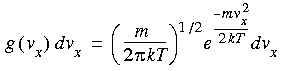
The x, y, z components of the velocities, on the other hand, have Gaussian distributions:
Eq. 87
 How initial velocities are generated
The initial velocities are generated from the Gaussian distribution of vx, vy, and vz. The Gaussian distribution is generated from a random number generator and a random number seed.
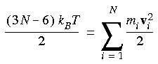
How temperature is calculated
Temperature is a thermodynamic quantity, which is meaningful only at equilibrium. It is related to the average kinetic energy of the system through the equipartition principle. This principle states that every degree of freedom (either in momenta or in coordinates), which appears as a squared term in the Hamiltonian, has an average energy of kT/2 associated with it. This is true for momenta pi which appear as pi2/2m in the Hamiltonian.
Hence we have:
Eq. 88
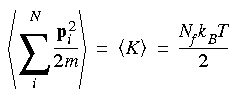 The left side of Eq. 88 is also called the average kinetic energy of the system, Nf is the number of degrees of freedom, and T is the thermodynamic temperature. In an unrestricted system with N atoms, Nf is 3N because each atom has three velocity components (i.e., vx, vy, and vz).
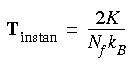
Instantaneous kinetic temperature
It is convenient to define an instantaneous kinetic temperature function:
Eq. 89
 The thermodynamic temperature
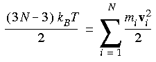
The average of the instantaneous temperature Tinstan is the thermodynamic temperature T.
Eq. 90
 Six degrees of freedom are subtracted because both the translation and rotation of the center of mass are ignored.
And for a periodic system:
Eq. 91
 Only the three degrees of freedom corresponding to translational motion can be ignored, since rotation of a central cell imposes a torque on its neighboring cells.
How temperature is controlled
Although the initial velocities are generated so as to produce a Maxwell-Boltzmann distribution at the desired temperature, the distribution does not remain constant as the simulation continues. This is especially true when the system does not start at a minimum-energy configuration of the model. This occurs often, since the model is commonly minimized only enough to eliminate any hot spots.
To maintain the correct temperature, the computed velocities have to be adjusted appropriately. In addition to maintaining the desired temperature, the temperature-control mechanism must produce the correct statistical ensemble. This means that the probability of occurrence of a certain configuration obeys the laws of statistical mechanics.
Only temperature-control methods used in MSI's simulation engines (Table 20) are considered here:
| method | simulation engine | ||
|---|---|---|---|
| CHARMm | Discover | OFF | |
|
Velocity scaling1
|
|
|
|
|
Berendsen temperature bath2
|
|
|
|
|
Nosé
|
|
|
|
|
Nosé-Hoover3
|
|
4
|
|
|
Andersen
|
|
4
|
|
To access the controls used for specifying the temperature-control method:
|
Direct velocity scaling can not be used to generate realistic thermodynamic ensembles, since it suppresses the natural fluctuations of a system. |
In Discover, the velocities of all atoms are scaled uniformly as follows:
Eq. 92
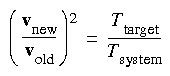 In the Cerius2·Dynamics Simulation module, the rescale factor is:
Eq. 93
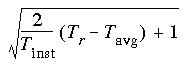 where Tinst = the instantaneous temperature, Tr = the required temperature, Tavg = the average kinetic temperature, and the term under the root is positive. Otherwise, rescaling is not done.
Direct temperature scaling adds (or subtracts) energy from the system efficiently, but it is important to recognize that the fundamental limitation to achieving equilibrium is how rapidly energy can be transferred to, from, and among the various internal degrees of freedom of the model. The speed of this process depends on the energy expression, the parameters, and the nature of the coupling between the vibrational, rotational, and translational modes. It also depends directly on the size of the system, larger systems taking longer to equilibrate.
Berendsen method of temperature-bath coupling
After equilibration, a more gentle exchange of thermal energy between the system and a heat bath can be introduced through the Berendsen et al. (1984) method (referred to as temperature damping in Cerius2·Dynamics Simulation), in which each velocity is multiplied by a factor  given by:
Eq. 94
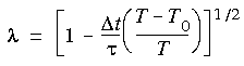 where t is the timestep size,
  is a characteristic relaxation time, T0 is the target temperature, and T the instantaneous temperature. (generally between 0.1 and 0.4 ps).
Nosé and Nosé-Hoover dynamics
Produces true canonical ensembles...
Nosé dynamics (Nosé 1984a, 1984b, 1991) is a method for performing constant-temperature dynamics that produces true canonical ensembles both in coordinate space and in momentum space. The Nosé-Hoover formalism (referred to as Nosé in Discover and as Hoover in Cerius2·Dynamics Simulation) is based on a simplified reformulation by Hoover (1985), which eliminates time scaling and therefore yields trajectories (Dynamics trajectories) in real time and with evenly spaced time points. The method is also called the Nosé-Hoover thermostat.
...through use of a fictitious mass
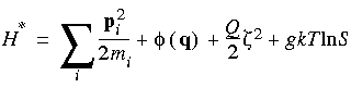
The main idea behind Nosé-Hoover dynamics is that an additional (fictitious) degree of freedom is added to the model, to represent the interaction of the model with the heat bath. This fictitious degree of freedom is given a mass Q. The equations of motion for the extended (i.e., model plus fictitious) system are solved. If the potential chosen for that degree of freedom is correct, the constant-energy dynamics (or the microcanonical dynamics, NVE) of the extended system produces the canonical ensemble (NVT) of the real model.
The Hamiltonian H* of the extended system is:
Eq. 95
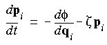
 Equations of motion for the real-atom coordinates q and moments p, as well as for the fictitious coordinates S and momentum
  (where
  is the interaction potential) are:
Eq. 96

Eq. 97
Eq. 98
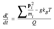 where Q = the user-defined q_ratio X a constant X g X T;
g = number of degrees of freedom;
T = temperature.
The choice of the fictitious mass Q of that additional degree of freedom is arbitrary but is critical to the success of a run. If Q is too small, the frequency of the harmonic motion of the extended degree of frequency is too high. This forces a smaller timestep to be used in integration. However, if Q is too large, the thermalization process is not efficient--as Q approaches infinity, there is no energy exchange between the heat bath and the model.
Q should be different for different models--Nosé (1991) suggests that Q should be proportional to gkBT, where g is the number of degrees of freedom in the model, kB is the Boltzmann constant, and T is the temperature.
In the Cerius2·Dynamics Simulation module, the factor that you can control directly is
, a relaxation time for the model (2 is directly proportional to Q). can be chosen as the second moment of the velocity autocorrelation function. For covalently bonded models, however, it is better to choose based on the frequencies involved in the model. on the same order as the smallest time scale (highest frequency) of your model.
Tests on polypropylene indicate that Nosé-Hoover dynamics needs a timestep of 0.5 fs with the velocity Verlet method in order to approach within 3% of the target temperature of 298 K. In contrast, 1.0 fs is sufficient for the direct velocity scaling method of temperature control.
For energy to be conserved, the Nosé-Hoover method also requires an accurate integrator. Thus, the ABM4 integrator, if available, with 0.5 fs as the timestep should be used.
Andersen method
One version of the Andersen method of temperature control involves randomizing the velocities of all atoms at a predefined "collision frequency". (The other version involves choosing one atom at each timestep and changing its velocity according to the Boltzmann distribution.)
This section includes:![]()
Pressure and stress
What are pressure and stress?
Pressure is another basic thermodynamic variable that defines the state of the system. It is a familiar concept, defined as the force per unit area. Standard atmospheric pressure is 1.013 bar, where 1 bar = 105 Pa. A single number for the pressure implies that pressure is a scalar quantity, but in fact, pressure is a tensor of the more general form (McQuarrie 1976):
Eq. 99
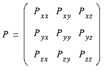 Each element of the tensor is the force that acts on the surface of an infinitesimal cubic volume that has edges parallel to the x, y, and z axes. The first subscript refers to the direction of the normal to the plane on which the force acts, and the second subscript refers to the direction of the force.
Eq. 100
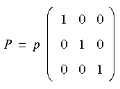 where the scalar quantity p is the equivalent hydrostatic pressure.
Units and sign conventions for pressure and stress
Pressure and stress can be expressed in many different units. The most common ones are bar and GPa. In SI units, 1 bar = 105 N m-2 and 1 GPa = 109 N m-2. Hence, 1 GPa = 104 bar. Pressure is usually expressed in bars, but in materials science, stress is often expressed in terms of GPa.
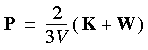
How pressure and stress are calculated
Pressure is calculated through the use of the virial theorem (Allen and Tildesley 1987). Like temperature, pressure is a thermodynamic quantity and is, strictly speaking, meaningful only at equilibrium.
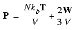
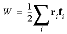
Thermodynamic pressure, thermodynamic temperature, volume, and internal virial can be related in the following way:
Eq. 101
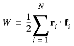
![]() And W is defined as:
And W is defined as:
Eq. 102
 Volume (and pressure) is known only for periodic models
Note that pressure is defined only when the system is placed in a container having a definite volume. In a computer simulation, the unit cell under periodic boundary conditions is viewed as the container. Volume, pressure, and density can be calculated only when the model is recognized as periodic.
Analogous to the temperature, an instantaneous pressure function P can be defined so that thermodynamic pressure is the average of the instantaneous values:
Eq. 103
 where P is the instantaneous pressure and T is the instantaneous kinetic temperature, which is related to the instantaneous kinetic energy K of the system as:
Eq. 104
 The instantaneous pressure function can be written as:
Eq. 105
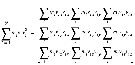
 Instantaneous pressure tensor
As mentioned above, pressure is a tensor and its components can also be expressed in tensorial form. Eq. 101 can be recast in the form of:
Eq. 106
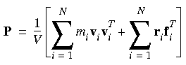 In detail, the two terms on the right-hand side of the equation are:
Eq. 107
Eq. 108
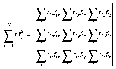 Instantaneous hydrostatic pressure
where rix, vix, and f ix indicate the x components of the position, velocity, and force vectors of the ith atom, respectively.
When periodic boundary conditions are used, atoms in the unit cell interact not only with the other atoms in the unit cell but also with their translated images. Forces on the images in the virial W must be included correctly. If the interaction is pairwise, using Newton's third law, W can be written as:
Eq. 109
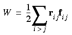 instead of:
Eq. 110
 Berendsen et al. (1984) use the rij · fij formalism by evaluating the virial and the kinetic energy tensor based on the centers of mass, which is valid because the internal contribution to the virial is canceled (on the average) by the internal kinetic energy. Because of the way forces are evaluated, rescaling of coordinates is also done on the basis of the centers of mass of the models.
The Discover program, however, calculates pressure on an atomic basis and performs atomic scaling. The major advantage of using atomic scaling of the coordinates is that atom overlapping can be avoided. Such overlap can occur if centers of mass are moved instead of individual atoms. In addition, for large models having internal flexibility, atomic scaling yields a smoother response to pressure changes.
In the Discover program, when explicit images (also called ghost atoms) are used under periodic boundary conditions, the rij · fij formalism is used, with the explicit images included.
How pressure and stress are controlled
As with temperature (How temperature is controlled), the pressure (and stress) -control mechanism must produce the correct statistical ensemble. This means that the probability of occurrence of a certain configuration obeys the laws of statistical mechanics.
Methods of controlling pressure
Only pressure-control methods used in MSI's simulation engines (Table 21) are considered here:
| method | simulation engine | ||
|---|---|---|---|
| CHARMm | Discover | OFF | |
|
Berendsen pressure "bath"
|
|
|
|
|
Andersen
|
|
1
|
|
|
Parrinello-Rahman
|
|
1
|
|
| 1
CDiscover only, not in FDiscover.
|
Choosing the pressure- and/or stress-control method(s)
To access the controls used for specifying the pressure- and stress-control methods:
How it works
The Berendsen method (Berendsen et al. 1984) couples the system to a pressure "bath" to maintain the pressure at a certain target. The strength of coupling is determined both by the compressibility of the system (using a user-defined variable
 ) and by a relaxation time constant (a user-defined variable ). At each step, the x, y, and z coordinates of each atom are scaled by the factor:
Eq. 111
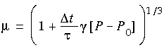 where t is the time step, P is the instantaneous pressure, and P0 is the target pressure. The Cartesian components of the unit cell vectors are scaled by the same factor µ.
Note that this method (as implemented) changes the cell uniformly, so that the size of the cell is changed, but not its shape. Therefore, for simulations such as crystal phase transitions, where both the cell size and shape are expected to change, this method is not appropriate.
The pressure fluctuation has been observed to be large during test runs with the Discover program and in studies in the literature (Brown and Clark 1984).
To compensate for the missing long-range part of the potential contributions to the energy, pressure at r > rc can be estimated by assuming the radial distribution g (r) ~ 1 (uniform distribution) in that region. With this assumption and the known form of nonbond potentials, the correction can be estimated analytically (Allen and Tildesley 1987).
Andersen method of pressure control
Change in cell size but not shape
With the Andersen method (1980) of pressure control, the volume of the cell can change, but its shape is preserved by allowing the cell to change isotropically.
The Anderson method is useful for liquid simulations since the box could become quite elongated in the absence of restoring forces if the shape of the cell were allowed to change. A constant shape also makes the dynamics analysis easier.
The basic idea of the method is to treat the volume V of the cell as a dynamic variable in the system. The Lagrangian of the system is modified so that it contains a term in the kinetic energy with a user-defined mass M and a potential term which is the pV potential derived from an external pressure Pext acting on volume V of the system.
Parrinello-Rahman method of pressure and stress control
Both size and shape of cell can change
The Parrinello-Rahman method of pressure and stress control can allow simulation of a model under externally applied stress. This is useful for studying the stress-strain relationship of materials. Both the shape and the volume of the cell can change, so that the internal stress of the system can match the externally applied stress.
The method is presented in detail by Parrinello and Rahman (1981) and is only summarized here.
 is related to the pressure and volume or the stress and strain of the system. The equations of motion for the atoms and cell vectors can be derived from this Lagrangian. The motion of the cell vectors, which determines the cell shape and size, is driven by the difference between the target and internal stress.
Eq. 112
 where h = {a · b · c} is the cell vector matrix, G = h´h, ri = hsi, is the interaction potential, and is the volume of the cell. The dots above some symbols indicate time derivatives and the primes indicate matrix transposition. Tr is the trace of a matrix. is replaced by:
Eq. 113
![]() where S is the applied stress, 0 is the initial volume, and
where S is the applied stress, 0 is the initial volume, and  is the strain; is also a tensor, defined as (h0´-1 Gh0-1 - 1)/2.
Note the user-defined variable W, which determines the rate of change of the volume/shape matrix.
In addition to relatively simple dynamics simulations, it is also possible to bias or control the dynamics run in several ways and/or to combine dynamics and minimization in one simulation. These types of dynamics runs can be used in conjunction with one or more of the various thermodynamic statistical ensembles (as appropriate, see Statistical ensembles).![]()
Types of dynamics simulations
Several such types of dynamics simulations are discussed in this section:
| method | simulation engine | ||
|---|---|---|---|
| CHARMm | Discover | OFF | |
|
Quenched dynamics
|
|
1
|
|
|
Simulated annealing
|
2
|
1
|
|
|
Consensus dynamics
|
|
3
|
|
|
Impulse dynamics
|
|
4
|
|
|
Langevin dynamics
|
|
|
|
|
Stochastic boundary dynamics
|
|
|
|
To access the controls used for specifying types of dynamics simulations:
A common limitation of classical minimization algorithms is that they usually locate a local minimum close to the starting configuration, which is not necessarily the global minimum (Local or global minimum?). This is because the minimizers discussed under Minimization algorithms are specifically designed to ignore configurations if the energy increases.
By using the available thermal energy to climb and cross conformational energy barriers, dynamics provides insight into the accessible conformational states of the molecule that would be inaccessible to classical minimization.
Quenched dynamics
How it works
In quenched dynamics, periods of dynamics are followed by a quench period in which the structure is minimized. You can specify the simulation time between quenches and the number of minimization steps. The quenched structure can then be written to a trajectory file (Dynamics trajectories), and dynamics continues with the prequenched structure.
Quenched dynamics is a way to search conformational space for low-energy structures.
Simulated annealing
How it works
In simulated annealing, the temperature is altered in time increments from an initial temperature to a final temperature and back again. This cycle can be repeated. The temperature is changed by adjusting the kinetic energy of the structure (by rescaling the velocities of the atoms).
Simulated annealing cannot be combined with impulse dynamics (Impulse dynamics).
Annealing allows the energy of the structure to be changed gradually, without allowing the structure to become trapped in a conformation that has a lower energy than nearby conformations but a higher energy than more distant conformations (that is, in a local energy minimum).
Consensus dynamics
How it works
Consensus dynamics can be thought of as an extension of the tethering restraint technique (Template forcing, tethering, quartic droplet restraints, and consensus conformations). In tethering, a model system serves as a fixed template. The "moving" system, driven by molecular mechanics or dynamics, is then forced to conform to the template by applying restraints.
In contrast, the consensus technique allows the "template" to respond to changes in the "moving" system, by treating all the models as "moving templates". The net result is that both models change so that their structures become similar. Consensus dynamics can be applied to more than two models simultaneously.
Consensus restraints have several uses. One example is the determination of structural similarities among a set of homologous compounds--perhaps several similar compounds that bind to a particular receptor. If you hypothesize that an apparently homologous region of the compounds is responsible for the binding, then you would want to find a configuration for this region that is compatible with relatively low-energy conformations for all the compounds. By applying consensus restraints to the homologous region of each compound, you can use dynamics followed by minimization to find a likely binding configuration.
Impulse dynamics
How it works
Impulse dynamics allows you to assign initial directional velocities to selected atoms before carrying out dynamics.
You can use impulse dynamics to push interacting molecules over energy barriers before allowing the structure to relax.
Langevin dynamics
How it works
The Langevin dynamics method (McCammon et al. 1976, Levy et al. 1979) approximates a full molecular dynamics simulation of a system by eliminating unimportant or uninteresting degrees of freedom. The effects of the eliminated degrees of freedom are simulated by mean and stochastic forces.
For example, instead of simulating hundreds of solvent molecules surrounding the solute molecules, the solvent can be ideally represented as a viscous fluid described in terms of dissipative and fluctuative equations.
Stochastic boundary dynamics
How it works
The stochastic boundary molecular dynamics method (Brooks et al. 1985a) uses a combination of both Langevin dynamics and Newtonian dynamics. With this method, the model is partitioned into a reaction region where Newtonian dynamics simulation is run, a buffer region where Langevin dynamics is run, and a reservoir region.
This allows detailed studies of spatially localized portions of interacting models. Enzyme-substrate interactions at the active site can be effectively studied using this technique.
Multibody order-N dynamics
The Insight·MBOND module and the standalone MBOND/CHARMm program (documented separately) is used for multibody order-N dynamics, in which models are substructured into a set of interconnected rigid and flexible bodies, as well as atomistic regions. The rigid bodies move as units, and the deformations of flexible bodies are represented by sets of low-frequency component modes. The atomistic regions are simulated by conventional dynamics. This method is another way of eliminating unimportant or uninteresting degrees of freedom and thus allowing a longer timestep to be used.
Constraints and restraints (Applying constraints and restraints) can be selectively applied during a dynamics run to save computing time and/or focus the simulation on more interesting parts of your model. For example, atoms can be specified as fixed or movable, and restraints can be applied in order to pull certain atoms towards one another.![]()
Constraints during dynamics simulations
Improving computational efficiency
Setting constraints during dynamics
To access the controls used for setting up SHAKE or RATTLE dynamics:
Bond vibrations constitute the highest frequencies in the system and thus determine the largest timestep that can be used during dynamics. If the bonds are constrained, longer timesteps can be used during dynamics, because of the absence of these high-frequency bond vibrations.
Although constraining bonds allows the timestep to be increased without incurring significant overhead for carrying out RATTLE iteratively, constraining angles does not really help to reduce the computational cost, because it takes a long time for the iterative procedure to converge. In some circumstances, it actually takes much longer than without RATTLE or SHAKE.
Tip
|
We do not recommend that angle constraints be used even though this functionality is available. However, if angle constraints have to be used, you should use a larger tolerance than with bonds. |
The SHAKE algorithm
Availability
The SHAKE method (Ryckaert et al. 1977), which is a popular algorithm for introducing distance constraints during molecular dynamics simulations, is used in CHARMm to constrain the harmonic stretching of bonds.
SHAKE may be applied to all bonds or only to bonds containing hydrogens, and to no angles, all angles, or only angles containing hydrogens.
Tip
|
To maintain a high degree of accuracy during the dynamics simulation, as well as to provide a larger integration time step, it is best to apply SHAKE only to bonds containing hydrogens. |
A twofold increase in the time step (to 0.001 ps) is enabled.
The RATTLE algorithm
What is the RATTLE algorithm
Constraints can be applied during dynamics runs via the RATTLE algorithm, which is the velocity version of SHAKE. The RATTLE procedure is to go through the constraints one by one, adjusting the coordinates so as to satisfy each in turn. The procedure is iterated until all the constraints are satisfied to within a given tolerance. Unlike SHAKE, RATTLE (Andersen 1983) makes sure that velocities are adjusted also, to satisfy the constraints, and is suitable for use with the velocity version of Verlet integrators.
RATTLE can be used to constrain bonds, angles spanned by two constrained bonds, as well as the distance between any pair of atoms in periodic and nonperiodic systems. It can be used with the constant-volume ensemble.
Note
|
For the time being, RATTLE cannot be used with constant-pressure dynamics, since that involves calculating the pressure on a molecule basis, which is not currently available. |
Dynamics in fixed-geometry water
Another major use of RATTLE is to enable the use of a fixed-geometry water model. With RATTLE, you can use the SPC, TIP3P, or current water models. The initial configurations of the water molecules are set to the equilibrium geometry of the SPC or TIP3P model or to the current geometry of water in your model.
What are trajectories?
![]()
Dynamics trajectories
The results of dynamics simulations can be saved in trajectory files, which are essentially a series of snapshots of the simulation taken at regular intervals. Trajectories can include data such as model structure, minimized-model structure (in quenched dynamics, see Quenched dynamics), temperature, energies, volume, pressure, cell parameters, and stress.
Trajectory files can be used for analysis of the results and also for continuing an interrupted dynamics simulation.
You can also animate trajectories, to view how the model behaved during a dynamics run.
To perform dynamics simulations, you need to know something about the general strategy of all types of dynamics simulations, and you need to know the general procedure for setting up a dynamics run.![]()
General methodology for dynamics calculations
Prerequisites
One of the most important steps in any simulation is properly preparing the system to be simulated. Calculations on the fastest computer running the most efficient dynamics algorithm may be worthless if the hydrogen is put on the wrong nitrogen or an important water molecule is omitted.
Stages and duration of dynamics simulations
Dynamics simulations are usually carried out in two stages, equilibration and data collection (or "production"). The duration of each stage depends on the system as well as on the purpose of the run.
For the equilibration stage, you typically assign random velocities to atoms in the model according to the Maxwell-Boltzmann distribution around the desired target temperature. Temperature control during the equilibration stage is usually by direct velocity scaling (Direct velocity scaling). Depending on your model and the purposes of your simulation, you may bring the simulated system up to the target temperature relatively quickly or in gradual steps.
The purpose of equilibration is to prepare the system so that it comes to the most probable configuration consistent with the target temperature and pressure.
One way to judge whether a model has equilibrated is to plot the various thermodynamic quantities, such as energy, temperature and pressure, versus time. When equilibration has been achieved, these quantities fluctuate around their averages, which remain constant over time. This is a necessary but not sufficient test, because it is not unusual for a sudden conformational change to occur after a long period of time.
After equilibrating the system at the target temperature and pressure, you can begin the production stage, during which data and statistics are collected. Temperature control during the production stage is generally by a more gentle, realistic method than direct velocity scaling (How temperature is controlled). You may use different thermodynamic ensembles (Statistical ensembles) during the equilibration and production stages.
Depending on the purpose of your study (Types of dynamics simulations), you may run several data-collection simulations under different conditions after a single equilibration run or stage.
How long should the simulation be?
One commonly asked question is how long to collect the statistics. The answer depends on both the properties being calculated and the model being simulated.
If a property varies randomly about a mean value with a decay time of t and the simulation is run for length T, the variance in the estimate is proportional to (t/T)0.5. When multiple independent fragments are present (for example, each water molecule in a solvent simulation), averaging can be done over the fragments to improve sampling.
Dynamics with MSI simulation engines
Prerequisites
To set up a dynamics run, first:
2. Set up the forcefield and prepare your model (Preparing the Energy Expression and the Model).
3. Run a preliminary minimization
Next:
5. Specify the desired output:
6. Review what you have requested for the run:
Finally:
For specific information on setting up and running dynamics with the various MSI simulation engines, and on analyzing the results, please see the relevant documentation (see Available documentation).
Restarting a dynamics simulation
You can continue a dynamics run without a break from the previous stage of the simulation, restart an interrupted run from where it ended, or start a new dynamics run from a particular point in a previous run.
With the Insight·Discover_3 module, continuing a run from one stage to the next (e.g., switching from equilibration to data collection or setting up complicated simulations) is straightforward: all stages can be specified when you set up the simulation, before starting the run. However, you may need to continue or restart a run, for any number of reasons.
The trajectory and other input file(s) that are required depend on what simulation engine is being used, and the exact procedure depends on whether you a continuing a run without a break from the last conformation of an immediately preceding run, restarting an interrupted run from the last conformation, or using an intermediate point of an earlier run as the basis for a new simulation.
Restarting a dynamics simulation
Briefly, the general procedure with each simulation engine is: