| Forcefield Based Simulations |
Who should read this chapter
Related information in this book
Forcefields presents the functional forms of energy expressions and describes the forcefields that are available in Molecular Simulations products.
The atom types defined for each forcefield are listed under Forcefield Terms and Atom Types.
The files that specify the forcefields are described in detail in separate documentation.
For specific information on procedures, please see the manual for the molecular modeling program and/or simulation engine that you are using (see Available documentation):
Graphic interface mode
![]()
Using forcefields
All MSI's simulation engines and forcefields can be used through at least one graphical molecular modeling interface (Cerius2, Insight II, QUANTA, see Table 1).
The Discover and CHARMm programs can also be run in a command-based, standalone mode with input from a text interface and/or a script and other input files.
For Discover and CHARMm, you can optionally perform some tasks through the appropriate graphical interface and others in standalone mode. For example, you might want to prepare model structure and command input files with the graphical interface, save both types of files, edit the command input file with a text editor so as to perform some complex simulation, start the run in standalone mode, and then analyze the results with the aid of one of the graphical interfaces. In addition, facilities exist for directly entering specific BTCL or CHARMm commands from the Insight or QUANTA interface and for reading a BTCL or CHARMm command input file into the Insight, Cerius2, or QUANTA interface.
How to run Discover and CHARMm in standalone mode is documented separately (see Available documentation).
Regardless of whether simulation engines are run through the graphical interface, in standalone mode, or in some combination of both modes, the general sequence of activities for doing forcefield-based calculations is as follows.
Important
|
For specific instructions, see the documentation for the appropriate simulation engine and/or molecular modeling program (see Available documentation). |
You should read this section if you want to understand what atom types are, how types and charges are assigned automatically, and how you can make your own atom type or charge assignments.
All molecular modeling programs supplied by MSI perform automatic and/or semi-automatic atom-type and charge assignment (which needs to be re-done if you switch to a different forcefield). Please see the guidebook for the appropriate molecular modeling program for details on how to assign atom types and charges for the simulation engine you are using (see Available documentation).
What are atom types in forcefields?
The simulation engine needs the forcefield atom type of each atom in the model in order to determine which forcefield parameters to use. Forcefield parameters apply to particular combinations of atom types as specified by the forcefield.
The forcefield atom types are related to the microchemical environment of the atoms in a way defined by the particular forcefield. For example, a methane model has only two atom types, one for the carbon and one for the hydrogens, even though each of the atoms may have a distinct atom name for labeling purposes. The hydrogen atoms are equivalent by symmetry; therefore, they would all have the same atom type in any forcefield.
Assigning atom types to a model
Atom types and charges supplied by the structure file
Atom types are assigned by the simulation engine or the molecular modeling program. Atom types are automatically assigned by using a set of rules that link the type of an atom to its element type and its chemical microenvironment (for example, the number and nature of connected atoms). Different forcefields use different atom types and atom-typing rules, which are contained in a residue library or the forcefield file.
To assure that you use the most appropriate atom types in your studies, you should always check the assigned atom types against the appropriate table under Forcefield Terms and Atom Types. In most cases, Cerius2 and Insight automatically assign the atom types. However, these assignment engines of course require the models to be correctly built. One of the most critical types of information is the bond order, which should be set before the forcefield is assigned.
Atom typing in different modeling programs
|
A newly assigned atom type (including associated parameters such as mass and charge) replaces any previously assigned or calculated value. |
Assigning charges
Charges (when available) are generally assigned at the same time as the forcefield atom type (see Assigning atom types to a model).
An atom-type charge is simply a fixed value associated with the atom types. Overall neutrality of a model is not necessarily achieved by assigning forcefield atom types. You may prefer to assign charges specifically. (The exact method depends on the molecular modeling program being used.)
Electrostatic interactions play a critical role in determining the structures of inorganic systems and in defining the packing of organic molecules.
Forcefields that include Coulombic terms generally already include standard charges (or "bond increments") associated with the atom types. These forcefields have been parameterized with nonzero atom type charges or charge increments (Table 6) and therefore you usually just assign charges automatically when you do atom typing, instead of having to assign specific charges:
| Forcefield | Engine |
|---|---|
|
CFF91-95, CFF, PCFF, COMPASS
|
OFF, Discover
|
|
CVFF
|
OFF, Discover
|
|
bks1.01
|
OFF
|
|
burchart1.01
|
OFF
|
|
burchart1.01-DREIDING2.21 (not all atom types)
|
OFF
|
|
burchart1.01-UNIVERSAL1.02 (Burchart atom types only)
|
OFF
|
|
glassff_1.01
|
OFF
|
|
MMFF93
|
CHARMm1
|
|
msxx_1.01
|
OFF
|
|
CHARMm
|
CHARMm
|
| 1
CHARMm as run through the Cerius2·MMFF module, not in QUANTA or standard CHARMm.
|
|
If you want to assign charges different from those in the forcefield, you need to assign the charges after atoms typing (and automatic charge assignment) is done. |
If you need to specifically assign charges, most relevant modules allow you to set atomic charges directly or specify an overall net charge for the whole structure using charge editing functions.
If you are a novice user or routinely run relatively simple calculations on relatively simple or standard models, you do not need to read this section. However, if, for example, an error message informs you of missing parameters or you want to customize your energy expression for an atypical model, then you do need to understand how the simulation engines determine what parameters are used for which atoms, bonds, angles, etc.
Determination of which parameters are used with which atom types
Before calculating the energy of a model, the simulation engine must construct the complete energy expression for the model by associating the correct forcefield parameters with the appropriate atoms and other coordinates. For example, methane has one type of bond (C-H) and one type of bond angle (H-C-H). The program must create a list of the four actual bonds and then associate the C-H bond parameters with each. Similarly, there are six H-C-H angles, but they are characterized by the same set of parameters.
Atom type equivalences
Chemically distinct atoms often differ in some, but not all, of their forcefield parameters. For example, the bond parameters for the C-C bonds in ethene and in benzene are quite different, but the nonbond parameters for the carbon atoms are essentially the same.
Wildcard atom types in the parameter file
For some internal coordinates, the parameters do not depend strongly on the specific atom types of one or more atoms. For example, the parameters of torsion terms may not be strongly affected by the end atoms. This means that the torsion parameters are essentially defined by the central bond rather than its substituents.
Automatic assignment of values for missing parameters
Availability
| Modeling program | Automatic parameters | Comments |
|---|---|---|
|
Cerius2
|
yes
|
not for all forcefields
|
|
Insight II (CDiscover)
|
yes
|
but not for AMBER forcefield
|
|
insight II (FDiscover)
|
yes
|
controllable in standalone mode only, not for AMBER
|
|
QUANTA
|
yes
|
but only if the PSF Generator is used
|
What happens if parameters are not found
Some classic and second-generation forcefields are not completely parameterized for all their atom types. (For rules-based forcefields (Rule-based forcefields broadly applicable to the periodic table), all parameters are generated according to rules rather than read from the forcefield file.) When parameters for classic and second-generation forcefields are not available, one of several things can happen, with varying consequences:
A forcefield may include automatic parameters for use when better-quality explicit parameters are not defined for a particular bond, angle, torsion, or out-of-plane interaction. These parameters are intended as temporary patches, to allow you to begin calculations immediately. While MSI has made every effort to ensure that the automatic parameters used in CVFF, the CFF family of forcefields, and CHARMm produce reasonable geometries for a wide variety of models, we cannot guarantee that the automatic parameters are appropriate in every instance. You therefore should always carefully evaluate any results that you obtain using automatic parameters.
Discover automatically assigns values for parameters missing from the CFF and CVFF forcefields by switching to an automatic forcefield. This switching is accomplished with an equivalence table that converts the original set of atom types to a smaller set of generic atom types.
In the automatic forcefield in the Discover program, the atom types for bonds, angles, torsions, and out-of-plane deformations have different levels of specificity. For example, while bond-stretching parameters are determined by the atom types of both atoms; angle-bending and torsion parameters may be determined by the atom type of only the central atom(s). A wildcard (*), representing any type of atom, is used for the end atoms of torsions and angles.
As an example, the parameters for the angle oh-c"-c" in oxalic acid (Figure 3) are not present in CFF91.
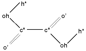
|
#auto_equivalence cff91_autoThus, for parameter assignment purposes only, atom type oh is reassigned to o_, c" is reassigned to c'_ for the apex atom, and c" is reassigned to c_ for the end atom. The parameters for the oh-c"-c" angle could be taken from either the o_c'_*7 or the c_c'_*9 lines in the quadratic_angle section of the cff91.frc file--o_c'_*7 is chosen because 7 is lower than 9:
! Equivalences
! -----------------------------------------------------------------------------
!Ver Ref Type NonB Bond Bond Angle Angle Torsion Torsion OOP OOP
Inct End Atom Apex Atom End Atoms Center Atoms End Atom Center Atom
!--- --- ---- ---- ---- --- -------- ----------- --------- ------------ -------- -----------
2.0 2 c" c" c" c'_ c_ c'_ c_ c'_ c_ c'_
2.0 2 oh o o_ o_ o_ o_ o_ o_ o_ o_
...
#quadratic_angle      cff91_auto

> E = K2 * (Theta - Theta0)^2

!Ver  Ref     I      J      K       Theta0         K2
!---- ---   ----   ----   ----   ---------    ---------
 2.0   2      c_     c'_    *9    120.0000       40.0000
 2.0   2      n_     c'_    *8    120.0000       53.5000
 2.0   2      o_     c'_    *7    110.0000      122.0000
 2.0   2      o'_    c'_    *6    120.0000       68.0000
 2.0   2      h_     c'_    *2    110.0000       55.0000
 ...
Missing and/or automatic parameters are also listed in an output file after the completion of a simultion run. You can find out if parameters are missing before starting your run:
Editing a forcefield
Expert users can edit MSI forcefields in different ways to customize them to their needs or to create new forcefields.
MSI's principal molecular modeling programs include forcefield editors (see Available documentation):
Expert users can edit the files that define many forcefields with a text editor:
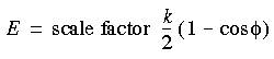
The energy expression is the heart of the forcefield. Potential energy is described in the energy expression as the sum of various terms that indicate the energy costs of bond stretching, angle bending, etc. Not all terms are present in all forcefields, and the functional forms of the terms vary among forcefields (see Forcefields). ![]()
Using alternative forms of energy terms
This section and the following main section (Applying constraints and restraints) describe energy term preferences that you can set and restraint terms that can be optionally included in the energy expression.
If you are a novice user, you should alter the default energy terms and parameters as little as possible. One exception to this recommendation is nonbond methods (see Handling nonbond interactions), where you should choose the method according to the model type rather than necessarily accept the default settings.
You may, for example, want to save computation time during the early stages of minimization of a model that is far from its equilibrium conformation by not calculating any cross terms. Or you may have found that certain terms are insignificant with respect to the purposes of your study.
You can effectively remove terms from the energy expression in several ways:
The contributions of various terms in the potential energy expression to the total energy can be scaled up or down and/or otherwise edited. This can be useful, for example, in the early stages of minimizing very "bad" structures, where large contributions by certain terms might interfere with convergence.
The Cerius2·Force Field Editor module allows you to directly change the parameters in any term (e.g., for all C_3-H_ bond terms, but not for all bond terms) in the forcefield. The Energy Terms control panels include entry boxes for all relevant parameters.
Alternative bond terms
With the CVFF forcefield in Discover, you can choose to use quadratic bond terms rather than Morse bond terms. The Morse term can allow bonds to stretch to unrealistic lengths (Figure 2), so you may get quicker convergence from a hightly distorted configuration if you replace the Morse term by a harmonic term. You do this by specifying the "no Morse" version of CVFF.
Scaled torsion terms
If all torsions about a common bond were simply summed, the torsion energy term could be too large. Cerius2·OFF therefore allows several methods for scaling torsion terms (Discover and CHARMm automatically handle torsions optimally, because of how their forcefields are parameterized):
Figure 4
. Torsion exocyclic to an aromatic ring
In Cerius2·OFF, you may use the first inversion term found or the average of all inversion energies, but the first approach is not recommended.
You can use the DSL (the FDiscover command language) set command to choose between the usual Lennard-Jones 6-12 or 6-9 potential (e.g., term 10 in Eq. 23) and a quartic form:
Eq. 26
![]() The quartic form is useful when you need to eliminate bad van der Waals contacts, but the second derivatives are not calculated.
The quartic form is useful when you need to eliminate bad van der Waals contacts, but the second derivatives are not calculated.
Hydrogen bonds and hydrogen-bond terms
Who should read this section
Many forcefields, especially the newer ones, fully account for hydrogen bonds by other terms in the forcefield and so do not have or require specific terms for handling hydrogen bond interactions.
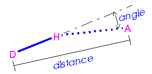
If specific hydrogen bonds are required, generation of a list of hydrogen bonds is a major step in evaluating the energy of a system. This process involves looking at all possible pairs of hydrogen bond donors and acceptors and selecting those that meet certain criteria (Figure 5):
Figure 5
. Distance and angle criteria for hydrogen bonds
A = hydrogen acceptor; D = hydrogen donor.
In Cerius2·OFF, the hydrogen bond criteria can be changed by using the Hydrogen Bond Preferences control panel (accessed by selecting the Energy Terms/Hydrogen Bond menu item from the OPEN FORCE FIELD card). This control panel also allows specification of switching function ("spline") parameters.
Bond-angle cross terms vs. Urey-Bradley terms
An alternative or supplement to bond-angle interactions is the Urey-Bradley term, which accounts for 1-3 interactions between two atoms that are bonded to a common atom.
Why read this section
![]()
Applying constraints and restraints
Constraints and restraints allow you to focus the calculation on a region or conformation of interest and also to set up computational experiments. Such experiments are one of the primary uses of molecular modeling, allowing you control over a model at the atomic level. Several examples are described under When to use constraints/restraints.
The seminal difference between a constraint and a restraint is that a constraint is an absolute restriction imposed on the calculation, while a restraint is an energetic bias that tends to force the calculation toward a certain restriction (even though many people use these terms as if they were interchangeable).
Most restraints and constraints are available via the graphical UIFs:
Fixed-atoms example
For example, you can fix some atoms in space, not allowing then to move. For example, part of the structure of a molecule may have been well solved experimentally, but the structures of other areas are less clear. Or you might want to keep parts of your model (e.g., solvent molecules) rigid to decrease computational costs.
You can add extra terms to the energy expression to restrain or bias the system in certain ways. For example, if you are investigating the adiabatic energy barrier to rotation about a bond, you would restrain the value of that torsion and minimize the structure. Repeating this procedure for a set of torsion values in the range 0°-360° yields a complete energy profile for rotation about the bond. A similar process is used to generate phi/psi maps and other multidimensional energy surfaces in studies of model conformation.
If a substrate is being docked onto an enzyme and a specific hydrogen bond between the enzyme and the ligand is thought to be involved in binding, the donor and acceptor atoms can be pulled together to provide a docking coordinate. In this way, the results are not so dependent on the initial starting configuration, which may have been only a crude graphic alignment. In cases like this, the restraint is turned off at some point to make sure that the biased minimum is close to a true minimum.
Another example of the use of restraints is in modeling incomplete systems. Often, it is difficult or impossible to construct a realistic environment around parts of a model system. For example, only a partial structure of a large protein complex may be available, and some atoms must be restrained to stay near their initial crystal positions because they do not "feel" interactions with neighboring (missing) amino acids, membrane, or solvent. If the site of interest (for instance, a binding site for a competitive inhibitor) is well characterized but other parts of the enzyme are unknown or would require too much computation time if they were included, a limited study can still be carried out with the ends tethered to their crystal coordinates. Usually, these restraints are permanent parts of the model. The results of such calculations must be critically evaluated but can be valid if the ligand binding does not depend on interactions with missing pieces of the model or on conformational flexibility in the tethered regions.
As a final example, tethering can be used to gently relax a crystal structure. Often, crystal coordinates, even if highly refined, have several strained interactions due to intrinsically disordered or poorly defined atomic positions, which, upon minimization, give rise to large initial forces. If these forces are not restrained, they can result in artifactual movement away from the original structure. The general approach is to progressively relax parts of the model in stages, starting with the least well determined atoms, until the entire system can minimize freely. The restraints are ultimately removed so that the final minimum represents an unperturbed conformation. It is usually not necessary to minimize to convergence at each stage--the object is to relax the most-strained parts of the system as quickly as possible without introducing artifacts.
Fixed atom constraints
Cost-saving
Use atom constraints when you want to apply minimization or dynamics to part of a model, while keeping the remainder of the model fixed and rigid. For example, use atom constraints to quickly minimize a sorbate in a zeolite by fixing the atom positions of the zeolite frame and allowing only the sorbate atoms to move. Or fix all residues in a protein except for those in the active site.
Template forcing, tethering, quartic droplet restraints, and consensus conformations
Uses
Typical uses of these related types of restraints are to bias the conformation of one model towards that of another, to bias selected atoms towards their experimentally known positions, to restrain the core of a model while allowing its solvent-exposed constituents more freedom of movement, or to find an identical or close set of conformations that a group of related models can achieve.
To force the conformation of one model to be similar to that of a template model, a one-to-one correspondence between atoms in the template and in the moving structure is set up, and (for example) one of the following restraint terms is added to the energy expression:
Eq. 27
 or:
or:
Eq. 28
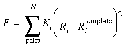 The term in Eq. 27 is proportional to the root-mean-square (rms) deviation of the analog atoms from the template atoms. (This form cannot be used with the Newton-Raphson minimizer in FDiscover.) The values obtained for the energy and the rms function depend on the value of the forcing parameter K. Typical values for this constant are in the neighborhood of 5 kcal Å-1. It is often instructive to look at the dependence of the energy and rms functions on the forcing parameter by making several determinations with different forcing parameters. If several runs (minimization or dynamics) are made, it may also be helpful to plot the energy as a function of the rms value. For tethered minimizations, a very large forcing constant (e.g., 2000.0 kcal Å-1) is often used to prevent significant movement of any of the tethered atoms.
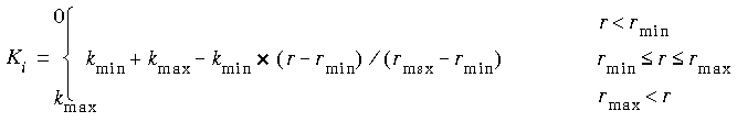
Eq. 28 represents a conceptually more straightforward restraint, with each atom restrained by an isotropic spring to the position of its template atom. In either form, the summation is over a list of pairs of atoms to restrain: one from the moving model, and one from the template model. FDiscover uses this quadratic form by default.
The Ki in Eq. 28 are determined by the distance of atom i from the atom defining the origin as:
Eq. 29
![]() where V is any appropriate internal (bond length, angle, etc.--the same functional form is used for several types of restraints).
where V is any appropriate internal (bond length, angle, etc.--the same functional form is used for several types of restraints).
The first form (Eq. 27) gives the best rms fit for the least energetic cost, but individual atoms may remain quite far from their template position. The second form (Eq. 28) restrains each atom individually, so each atom is forced toward its template partner. The resulting rms fit is not as good as that from Eq. 27, but no one atom is allowed to deviate as much as is possible with Eq. 27. The form in Eq. 28 also allows for a different force constant for each pair, which means that different atoms or classes of atoms can be treated differently.
Tethering is the same as template forcing, except that the atoms are restrained to their original positions rather than to positions in a template structure. Both Eq. 27 and quadratic forms are applicable for tethering; however, Eq. 28 is used by FDiscover and Eq. 29 by CDiscover, because tethering is usually used to keep atoms from moving too far from their original positions.
CHARMm allows mass-weighted tethering by calculating an additional energy term for all atoms that are to be restrained. This term has the form:
Eq. 30
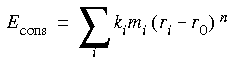 Where Econs is the constraint energy, ki is the force constant, mi is the mass of atom i (if mass weighing is used) or 1, ri is the position of atom i, r0 is the reference position about which the atom is to be centered, and n is an exponent.
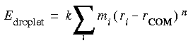
The quartic droplet restraint term in CHARMm is designed to put the entire model into a "cage" by constructing a restraining sphere around a model. The potential is scaled so that atom positions furthest from the center of mass or the geometric center of the model have the greatest restraining force applied.
Eq. 31
 FDiscover (standalone only) allows similar restraints within spherical shells.
Consensus dynamics is used to find the consensus configuration of a set of analogs. In essence, all models in the set are treated as both moving molecules and templates.
The database capability of CDiscover is used in settng up consensus dynamics calculations, using the restraint in Eq. 29.
General internal-coordinate restraints
In CHARMm, you can apply general internal coordinate restraints by applying restraints to all bonds, angles, and/or dihedral angles that have entries in an internal coordinates table. This facility is global, that is, not applicable to specific internal coordinates.
Distance and NOE restraints
Uses
Distance restraints are used to bias the distance between two atoms, bonded or not, toward a given value. Some uses are to cyclize linear models by bringing the ends closer together, dock different models, and fit distance data derived from NOE and other experiments.
Several commonly used functional forms are supported.
Eq. 32
![]() where K is a force constant, Rij is the current distance between the atoms, and Rtarget is the target distance. A large force constant tends to force the distance to be close to the target distance; a smaller force constant results in a correspondingly smaller bias.
where K is a force constant, Rij is the current distance between the atoms, and Rtarget is the target distance. A large force constant tends to force the distance to be close to the target distance; a smaller force constant results in a correspondingly smaller bias.
In Cerius2, the form is the same, except that K is multiplied by 0.5. Rtarget can be defined explicitly or automatically extracted from the model as the current distance between atoms.
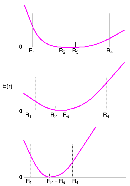
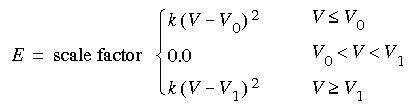
The second form is also harmonic, but it is separated into several piecewise continuous regions, resulting in a flat-bottomed potential (Figure 6). For FDiscover, the form is:
|
 where V is any appropriate internal (bond length, angle, etc.--the same functional form is used for several types of restraints).
The restraining potential used in CHARMm is:
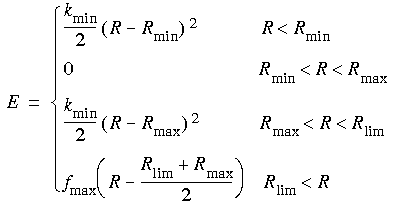 Where Rlim is the value of R where the force equals fmax.
...and cosine
CDiscover also allows a cosine form of restraint:
Eq. 36
![]() where V is any appropriate internal (bond length, angle, etc.) and n is the periodicity.
where V is any appropriate internal (bond length, angle, etc.) and n is the periodicity.
It is not necessary for the flat-bottomed potential (Figure 6) to be symmetric. By appropriate definition of the points R1, R2, etc., any of the regions may be eliminated. For Eq. 33, the important regions are those from R1 to R2 and from R3 to R4, where a harmonic potential is applied, and the flat bottom from R2 to R3.
This form of the restraint allows a range of acceptable distances and is particularly useful for incorporating experimental distance information, such as those from NOE experiments, into a calculation. The flat bottom allows for experimental error in the determined distance. The two outer regions (Figure 6) have a constant gradient, which is useful for avoiding unreasonably large forces if the initial structure is far from the target value.
Distance and angle constraints in dynamics simulations
The RATTLE and SHAKE algorithms effectively remove very-high-frequency vibrations from consideration during dynamics simulations. Use of these algorithms can allow for a larger time step during simulation.
Angle restraints
In Cerius2, an angle restraint can be applied to a group of any three atoms. The restraint is implemented such that:
Eq. 37
![]() Where: Ka is the angle force constant;
Where: Ka is the angle force constant;  is the angle between the selected atoms; and 0 is the desired restrained angle of the selected atoms. 0 can be defined explicitly or can be automatically extracted from the model as the current angle connecting selected atoms.
Some uses of torsion restraints are to enforce chiral and prochiral centers, prevent cis-trans conversions, and fit NOE J-coupling constants from NMR experiments. Conversely, other uses are to force torsion rotation in order to perform phi/psi mapping, perform conformational searching, and induce conformational changes.
Several forms of torsion restraints are used in the literature and implemented in MSI's simulation engines.
In Cerius2·OFF, a torsion (dihedral) restraint can be defined among any group of four atoms. The restraint is implemented such that:
Eq. 38
![]() Where Kt is the torsion force constant;
Where Kt is the torsion force constant;  is the angle between the i-j-k and j-k-l planes; and 0 is the desired restrained angle of the selected atoms, which can be defined explicitly or automatically extracted from the model as the current angle connecting selected atoms.
Eq. 39
 or trans:
Eq. 40
![]() or either cis or trans:
or either cis or trans:
Eq. 41
![]() You can also use the flat-bottomed function (Eq. 34) to apply J3 dihedral restraints to fit the results of NOE experiments. A plain cosine form (Eq. 36) and a quadratic form (Eq. 29) are also available. The torson involving any four atoms can be restrained.
You can also use the flat-bottomed function (Eq. 34) to apply J3 dihedral restraints to fit the results of NOE experiments. A plain cosine form (Eq. 36) and a quadratic form (Eq. 29) are also available. The torson involving any four atoms can be restrained.
In FDiscover, the functional forms include a simple harmonic form analogous to Eq. 32 and a piecewise continuous form like Eq. 33 with R interpreted as the angle, rather than the distance. Another form is the periodic function of Eq. 42:
Eq. 42
![]() where V gives the strength of the restraint, n is an integer periodicity, and 0 is the phase angle.
where V gives the strength of the restraint, n is an integer periodicity, and 0 is the phase angle.
Inversion, out-of-plane, and chiral restraints
Uses
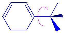
Typical uses include prevention of changes in chirality or prochirality. (A molecule is chiral if no stable conformation of it can be superimposed on its mirror image--most chiral organic molecules can be described in terms of chiral centers, i.e., an atom that has four distinct substituents. Two chemically identical substituents on an otherwise chiral tetrahedral center are prochiral; in addition, sp2 hybridised planar systems with three different substituents are considered prochiral.)
In Cerius2·OFF, an inversion (improper torsion or out-of-plane angle) restraint can be defined among any four atoms i, j, k, l, where i defines the inversion center. The restraint is implemented such that:
Eq. 43
![]() Where Ki is the force constant for the out-of-plane;
Where Ki is the force constant for the out-of-plane;  is the angle between the i-j-l and i-k-l planes; and 0 is the desired restrained out-of-plane angle of the selected atoms, which can be defined explicitly or automatically extracted from the model as the current angle connecting selected atoms. There must be a real atomic center for the inversion.
CDiscover can also impose a cosine (Eq. 36), quadratic (Eq. 29), or flat-bottomed (Eq. 34) out-of-plane restraint.
The FDiscover DSL language can be used to impose chirality and prochirality restraints having the same functional form as Eq. 43, where 0 is the out-of-plane angle corresponding to R or S.
Plane and other geometrical constraints and restraints
The BTCL language of CDiscover allows sophisticated geometric manipulation of molecular and other objects, including constraints and restraints, by means of the geometry, molGeom, restraint and other commands. A subset of this functionality is accessible in the Calculate/Geometric parameter block in the Insight·Discover_3 module.
Why read this section
![]()
Modeling periodic systems
Periodic boundary conditions refers to the simulation of models consisting of a periodic lattice of identical subunits. By applying periodic boundaries to simulations, the influence, for example, of bulk solvent or crystalline environments can be included, thereby improving the rigor and realism of a model.
| periodicity | engine | details |
|---|---|---|
|
minimum image
|
OFF1, FDiscover, CHARMm
|
here
|
|
explicit image
|
FDiscover, CDiscover, CHARMm
|
here
|
|
crystal simulations
|
OFF, CDiscover, CHARMm
|
here
|
|
bonds across boundaries
|
OFF, CDiscover, CHARMm
|
here
|
| 1
The Open Force Field module in Cerius2.
|
Most methods for controlling the treatment of periodic systems are available via the graphical UIFs:
Models are specified in Cartesian space
Some simulation engines accept only Cartesian coordinates, not crystal coordinates (others are able to convert between the two systems). This is important when using asymmetric space groups, since the symmetry operators assume that the input coordinates correspond to the standard asymmetric unit as defined in the International Tables for Crystallography (Reidl 1983).

|
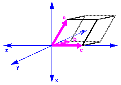
For Cerius2·OFF, by default the c lattice vector is parallel to the z Cartesian axis and the b lattice vector lies in the y,z plane (Figure 8).
|
CHARMm can handle models that are defined in either crystal or Cartesian space. In converting from crystal to Cartesian axes, the a, b, c crystal axes are aligned with the x, y, z Cartesian axes (Figure 7).
|
For periodic systems in which nonbond interactions dominate, the Ewald sum method (Ewald sums for periodic systems) is preferred over the the minimum-image convention. |
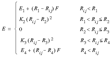
The left side of Figure 9 shows a solute molecule surrounded by enough solvent to occupy the volume (and shape) of a cube. A simulation carried out on this isolated cubic system is a poor approximation of what would happen in a true bulk solvent environment. For example, the solute can diffuse toward a surface or solvent molecules can evaporate. To remedy this, on the right of Figure 9 the cube is replicated in three dimensions to form a 3 X 3 X 3 lattice of identical cubes. This is a much better representation of bulk solvent for the interior cube, because molecules near the surfaces now interact with solvent in adjacent cubes. The imaged atoms are used to calculate energies and forces on the real atoms in the interior cube. The energies and forces on the imaged atoms themselves are not calculated because their motions are computed as symmetry operations on the real atoms, for example, by translations along the cubic axes.
Implications of minimum-image model for calculating nonbond interactions
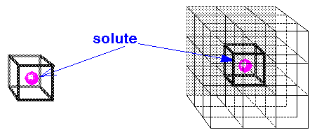
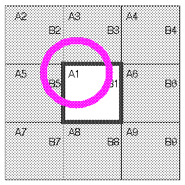
Consider the implications of this model for a specific case. In Figure 10, molecule A1 is located near an edge of the square. (For simplicity, this discussion focuses on a two-dimensional lattice.) In addition, eight images of A1 (A2-A9) are present in the adjacent symmetrically related squares. Consider the interactions of molecules A with molecules B. The closest image of B to A1 is actually not B1, but rather B5. If molecules in the interior cell are allowed to interact only with the molecule or molecular image closest to it, this is called a minimum-image model. Each molecule interacts only with those molecules and images within a distance of half the cell size. The advantage of this approach is its simplicity. It is straightforward to compute energy between a given pair of molecules without explicitly keeping track of the images in neighboring cells. All periodic boundary algorithms imply a cutoff criterion, but the minimum-image convention implies a maximum distance for this cutoff of no more than half the cell dimensions.
|
For a description of the minimum-image convention, see also Allen and Tildesley (1987).
Explicit-image model
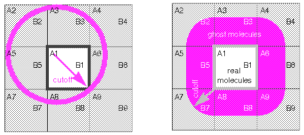
A more general approach--ghost molecules
Simulation engines (Discover and CHARMm) can also use a more general approach by generating explicit images of the interior molecules, also called ghost molecules, which interact with the interior molecules. These ghost molecules are replicated to as great a distance as necessary (but no farther than necessary) to satisfy the desired potential energy cutoff criteria.
Cutoff distances and nonbond interactions
The right side of Figure 11 shows which molecules in the adjacent unit cells become explicit ghost molecules for a given cutoff distance. Not every molecule in an adjacent cell becomes a ghost. However, if a cutoff distance that is longer than the cell length is used, ghosts from unit cells beyond the nearest neighbor cells may be included. As molecules (effectively, see below) move in and out of the boundaries, the molecules that are ghosts can change. Therefore, the ghost list is regenerated periodically.
Nonbond interactions do not have to be calculated between ghost atoms. This helps to significantly reduce computation time.
How images and "real" molecules move
Ghost molecules follow their symmetrically related counterparts. However, when it comes time to move the molecules (in a dynamics step or minimization iteration), only the real molecules (A1 and B1) are actually moved according to the accumulated forces each molecule has felt. The ghost molecule positions are simply regenerated by applying the defined symmetry relations to the new positions of the molecules.
Crystal simulations
Energies of crystals can be calculated and the lattice parameters a, b, c,  ,
,  , and
, and  can be optimized with Cerius2, CDiscover, and CHARMm:
Cerius2·OFF, CDiscover, and CHARMm can handle bonds across cell boundaries. (However, CHARMm is best used only for linear polymers, since it does not handle 3D lattices or networks well.)
Why read this section
Nonbond terms can involve extensive calculation. To avoid a heavy calculation burden, some approximation scheme is often employed. Choosing the best method for your particular model can save computational expense without sacrificing accuracy.
| method | type of system | engine | details |
|---|---|---|---|
|
atom-based (single) cutoffs
|
periodic, nonperiodic
|
OFF1, FDiscover, CDiscover, CHARMm
|
here
|
|
group-based cutoffs
|
periodic, nonperiodic
|
FDiscover, FDiscover, CHARMm
|
here
|
|
double cuttoffs
|
periodic, nonperiodic
|
FDiscover
|
here
|
|
tail corrections
|
disordered periodic
|
CDiscover
|
here
|
|
cell-based cutoffs
|
periodic
|
CDiscover
|
here
|
|
cell multipole method
|
nonperiodic, periodic2
|
CDiscover
|
here
|
|
Ewald sums
|
periodic
|
OFF, CDiscover
|
here
|
| 1
The Open Force Field module in Cerius2. 2 Standalone only for periodic systems, cannot be used for constant-pressure or constant-stress dynamics.
|
Most methods for specifying how to treat nonbond interactions are available via the graphical UIFs:
You may use different methods for van der Waals and electrostatic interactions
Typically, both van der Waals and Coulombic interactions are calculated by the same method and (if by the nonbond cutoff method) with the same nonbond list. However, different methods and parameters may be used for van der Waals and Coulombic terms in CDiscover and (except for some operations) in Cerius2·OFF and CHARMm. This allows you, for instance, to use a large cutoff for electrostatic interactions and a smaller cutoff for van der Waals interactions.
|
For models having 2D periodicity (e.g., built using the Cerius2·Surface Builder) the Ewald method is available for the Coulombic terms but not for the van der Waals terms. |
Van der Waals and Coulombic interactions are ordinarily calculated between all atom pairs that are not specifically excluded. Most forcefields exclude nonbond terms for atoms connected by bonds (1-2 interactions) and valence angles (1-3). Some forcefields also exclude nonbond terms between end atoms in torsion (1-4) interactions. These interactions are illustrated Figure 12.
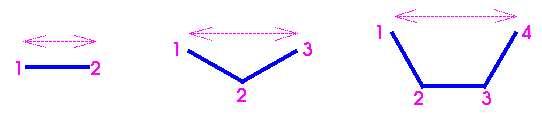
|
If 1-4 nonbond interactions in torsions are included in the nonbond list, they may be scaled. For example, with the AMBER forcefield (as implemented in both Cerius2·OFF and Discover) these nonbond interactions must be scaled by 0.50.
> scale 1-4 by 0.5
The equivalent BTCL command for the CDiscover program is forcefield scale with the vdw_1_4 keyword.
Combination rules for van der Waals terms
van der Waals radius combination rules
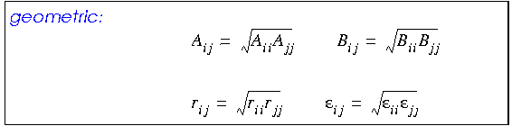
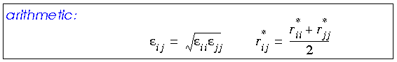
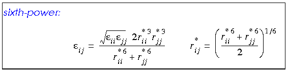
Any van der Waals interaction parameters that are actually defined for heterogenous atom pairs are called off-diagonal parameters. Off-diagonal parameters that are not available for such atom pairs are calculated by averaging those for each of the two atom types, using a geometric, arithmetic, or (in CDiscover and Cerius·OFF) 6th-power combination rule:
Eq. 44
Eq. 45
Eq. 46
 Availability
In Discover and Cerius2·OFF, a choice of combination rule is available and is specified in the forcefield file (see the File Formats documentation).
The arithmetic mean gives marginally better equilibrium distances for van der Waals interactions than the geometric combination rule (Halgren 1992). The 6th-power rule (not available with all forcefields) yields even better results (Waldman and Hagler 1993).
With the Ewald method (Karasawa & Goddard 1989) (Ewald sums for periodic systems), the geometric mean leads to faster convergence than the arithmetic mean.
In addition, because the Ewald sum calculation proceeds much faster when only diagonal parameters are used, the Cerius2·OFF Van Der Waals Preferences control panel includes an option to ignore off-diagonals even when they are present (they are not present in any of the Discover forcefields).
The dielectric constant and the Coulombic term
Role of the dielectric constant in modeling
The electrostatic potential is computed from the partial atomic charges associated with the model (Assigning charges). Approximate solvent-screening effects can be included by specifying a nondefault value for the dielectric constant  if it is explicitly included in the forcefield. (The "dielectric constant" used in modeling is not the dielectric constant that most experimental chemists would think of--it is instead an empirical, dimensionless scaling factor.)
The dielectric constant reflects the polarizability of the solvent molecules. A polarizable solvent such as water has a greater dielectric constant than less polar liquids. Electrostatic interactions in polarizable solvents with high dielectric constants are greatly attenuated. In closely packed molecules, however, there are fewer solvent molecules to screen the charge interactions.
For a helpful review, please see Harvey (1989). A tutorial on dielectric constants in forcefields can be found at MSI's website:
The dielectric constant can be kept constant, or the Coulombic term can be made a shielded function, where the dielectric "constant" is a function of distance (r ·
). This is useful for electrostatic interactions in closely packed molecules, where the number of solvent molecules between two interacting charges is usually fewer than in bulk solvent. A distance-dependent dielectric constant is also useful for models in which explicit solvent molecules are not included.
Important
|
A distance-dependent dielectric constant cannot be used on a periodic model with the Ewald sum method (Ewald sums for periodic systems). |
The dielectric constant can be changed and/or made distance dependent in any of MSI's simulation engines.
Special considerations for the AMBER forcefield
With the AMBER forcefield, in most applications a distance-dependent dielectric (
= f (r)) should be used.
> set dielectric = 4.0*r
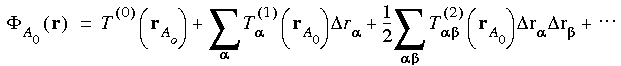
An energy expression such as Eq. 8, which is representative of current forcefields, is computationally tractable only for systems with relatively small numbers of atoms. The number of internal coordinates grows linearly with the size of a model, so the computational work involved in the first nine terms in Eq. 8 also grows linearly.
However, inspection of the final summation, which represents the nonbond interactions, reveals a quadratic dependence on the number of atoms in the system: If the system of interest has 1000 atoms, the nonbond summation has about 500,000 terms. If it has 10,000 atoms, the summation has 50,000,000!
|
The same nonbond method(s)1 and specifications should generally be used for all energy calculations within a given project. |
1. However, the method and/or specifications used for van der Waals interactions may differ from those used for Coulombic interactions (see You may use different methods for van der Waals and electrostatic interactions).
Effect of nonbond cutoff distance on calculation of nonbond interactions
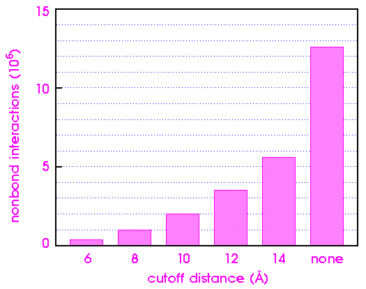
To appreciate the impact of cutoffs on computational efficiency, consider a receptor-ligand-solvent system with 5000 total atoms. An example would be a small protein (100-150 residues) surrounded by 1-2 layers of water.
The significance of nonbond interactions beyond the cutoff distance depends on the system being simulated. In modeling an isolated molecule or cluster, the use of cutoffs for the van der Waals interactions is quite reasonable. The potential is relatively short range and dies out as 1/r6. Consequently, by 8-10 Å, both the energy and forces are quite small.
|
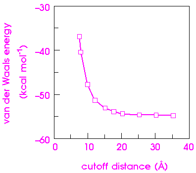
Figure 14 shows how the van der Waals component of the nonbond energy varies as a function of cutoff distance for an [Ala-Pro-D-Phe]2 crystal. The van der Waals energy changes by 40% as the cutoff distance is increased from 8 to 15 Å. The exact dependence of the energy on the cutoff distance depends on the system itself and should be calibrated for each new system.
|
Atom-based cutoffs and nonbond cutoff terms
Direct cutoff not recommended
MSI applications make several methods available for calculation of long-range nonbond interactions. Cerius2·OFF offers (among others) the direct method, which is straightforward and can be applied to nonperiodic and periodic models. Nonbond interactions are simply calculated to a cutoff distance and interactions beyond this distance are ignored.
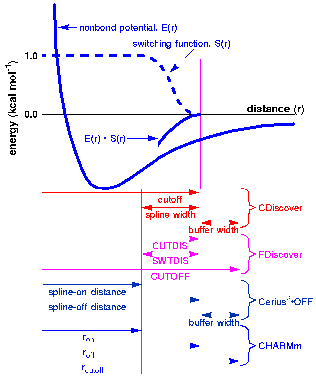
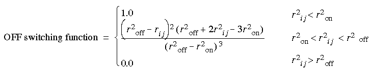
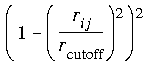
To avoid the discontinuities caused by direct cutoffs, most simulation engines use some kind of switching function (Figure 15) to smoothly turn off nonbond interactions over a range of distances. (The variable names and definitions differ among MSI simulation engines, as illustrated in the figure).
Cerius2·OFF allows you to use a cubic spline switching method, by which the energy is multiplied by a spline function. The interaction cutoff is defined by two parameters: the spline-on and the spline-off distances (Figure 15). Within the spline-on/spline-off range, the nonbond interaction energy is attenuated by the spline function. Beyond the spline-off distance, nonbond interactions are ignored. The current defaults in the Open Force Field module set a narrow on/off range that results in fast calculations. Using a broader spline range gives more accurate results, but slower calculation.
Eq. 47
 Implementation in Discover
In the Discover program the switching function is defined by two variables: the point where the function reaches zero and the range over which the function decreases from one to zero (Figure 15).
The Discover program uses a fifth-order polynomial for the switching function. It is formulated so that the first and second derivatives are zero at both the inner and outer ends of the switching region. Thus, the interaction energy and its first and second derivatives are continuous, although higher derivatives are not.
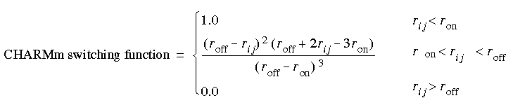
CHARMm and Cerius2·MMFF offer two types of switching functions, which its documentation refers to as a switching function (not the same as the Discover switching function) and a shifted potential.
Eq. 48
 However, energy can be significant at the cutoff distance, which can result in artificially large forces at long ranges. This is especially true for relatively short (that is, less than 12 Å) cutoff distances and small ranges (that is, when roff - ron < 3 Å).
Eq. 49
 One disadvantage to the CHARMm functions is a discontinuity in the second derivatives at the cutoff distance.
Neighbor lists and buffer widths
To maximize the efficiency of nonbond calculations, Cerius2·OFF, Discover, and CHARMm create a neighbor list that contains all pair interactions to be considered during calculation of the nonbond interactions. Atom pairs are not included in the list if they are too far apart or if they are excluded (Automatic exclusions).
Although a neighbor list requires time to set up, the net result is time saving for models containing more than about 50 atoms, because the list is not recalculated each time the energy expression is evaluated. Since the list is not updated at every step, it includes atoms in a buffer region (the distance between the two right-most lines in Figure 15) that might move close enough together to contribute to the energy calculation before the next update of the neighbor list.
To ensure that no atoms outside the buffer region can move close enough to interact during an energy minimization or molecular dynamics simulation, the nonbond list is automatically updated whenever any atom moves more than one-half the buffer width. Thus, the width of the buffer region, coupled with the velocity with which atoms move, determines the maximum amount of time before the neighbor list is updated.
Charge groups and group-based cutoffs
Dipoles must not be split by cutoff distances
To understand the implications of the generalization that the strongest electrostatic interactions in many molecules are due to dipoles rather than fully charged groups (see You may use different methods for van der Waals and electrostatic interactions), note that the interaction energy for two monopoles, each of one e.u. of charge, is about 33 kcal mol-1 at 10 Å, while that for two dipoles formed from unit monopoles is no more than about 0.3 kcal mol-1. It is clear that ignoring monopole-monopole interactions would give grossly misleading results, whereas ignoring dipole-dipole interactions would be only a modest approximation.
If nonbond cutoffs were applied to such a model on an atom-by-atom basis, this could generate spurious monopoles by artificially splitting dipoles (by having one of a dipole's atoms inside the cutoff and one outside). Instead of ignoring a relatively small dipole-dipole interaction, this would artificially introduce a large monopole-monopole interaction. To avoid these artifacts, the Discover and CHARMm simulation engines can apply cutoffs over charge groups. (In CHARMm in PSF mode, every residue is a charge group.)
A charge group is a small group of atoms close to one another which has a net charge of zero or almost zero. Often, charge groups are identical to common chemical functional groups. Thus, a carbonyl group, methyl group, or carboxylic group would be an approximately neutral charge group.
The Discover program designates one atom from each charge group as the switching atom and generates the neighbor list by considering the distance between the switching atoms of two charge groups. If the distance is less than the cutoff distance, then the pairwise interactions between all atoms in the two groups are included. If the distance is greater than the cutoff, they are all excluded. Similarly, when calculating the actual interaction energy, the Discover program switches off the interactions between all atom-atom pairs in the two charge groups based only on the distance between the two switching atoms. This procedure prevents artifactual splitting of dipoles.
If group-based cutoffs are used in CHARMm, the neighbor list is stored in terms of group pairs.
The size of a charge group, as defined by the greatest distance from the switching atom to another atom in the same group, must be significantly smaller than the cutoff distances. Otherwise, an interaction between two atoms close to each other might be ignored because the switching atoms of the two groups are farther apart than the cutoffs. Typical groups are no more than 1-3 Å large, so cutoffs larger than 7-8 Å are reasonable. However, some models contain considerably larger groups.
The Discover program also warns you about significantly non-neutral groups. Some can be expected if the model contains formally charged functional groups, such as protonated amines and carboxylates. However, other non-neutral groups usually indicate an error in group definitions.
In Cerius2·Discover, you can specify the tolerance with which neutrality is defined when you ask Discover to perform charge grouping.
Double cutoffs
The FDiscover program also incorporates an improvement over a single cutoff distance called double cutoffs, or, as it is sometimes called in dynamics, multiple timesteps. The nonbond interaction potential at a distance is a smooth function that does not vary rapidly.
It is important to realize that the effective potential energy surface is not quite continuous when double cutoffs are used. The magnitude of the discontinuities depends on the cutoff distances and the system that is being studied.
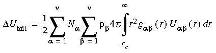
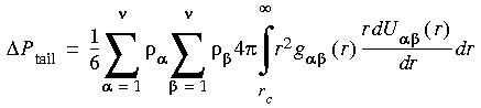
Tail corrections
Long-range van der Waals interactions in disordered periodic systems
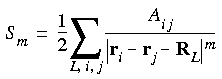
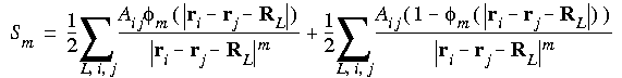
For disordered periodic systems, contributions to the potential energy and pressure from van der Waals interactions outside the cutoff can be written as:
Eq. 50
Eq. 51
 where Ni and
  i denote the number and number density of atoms of type i, U (r) denotes the van der Waals nonbond potential describing interactions between atoms of type and , and g (r) denotes the pair correlation function describing the probability of finding and at separation r relative to the probability of finding the pair at an infinite distance (McQuarrie, 1976, Chapter 13). (r) is short range, reaching its limiting value of unity at distances of ~10 Å. Moreover, g (r) - 1.0 is small even at shorter distances. In consequence, accurate estimates of the tail corrections for all normal nonbond cutoff values may be safely made by setting all g (r) = 1.0 in Eq. 50 and Eq. 51.
Note also that applying Eqs. 50 and 51 at each step in a simulation contributes negligibly to the overall simulation cost, since for constant-volume simulations the full correction may be precomputed, and in simulations where the volume fluctuates it is necessary only to recompute the volume at each step.
Cell-based cutoffs
CDiscover allows cell-based cutoffs for periodic systems. This is another image-based method, in which the neighbor list is based on a specified number of cell layers surrounding the central cell.
Cell multipole method
Mor rigorous, controllable, and efficient than cutoffs
The cell multipole method (CMM, available only in CDiscover) provides a treatment of the nonbond interactions for both nonperiodic and periodic systems that is more rigorous and efficient than cutoffs. This method (Greengard and Rokhlin 1987, Schmidt and Lee 1991, Ding et al. 1992) is a hierarchical approach that allows the accuracy of the nonbond calculation to be controlled. Short-range interactions are treated in the usual way, but long-range group-group interactions are treated in terms of multipoles. Computational time scales as N (the number of atoms).
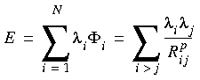
Eq. 52
 where
where  i is the potential at atom i, Rij is the distance between atom i and atom j, p is a number (p = 1 for Coulombic and 6 for London dispersion interactions, for example), and the
  's are general charges. For Coulombic interactions, the 's are real charges.
The general potential
i may be divided into a near-field potential due to the surrounding atoms (those within a few angstroms) and a far-field potential due to the rest of the atoms that interact with the ith atom.
We begin by placing an arbitrarily shaped molecule in a rectangular box. The box is then cubed into a number of basic cells of length 4-6 Å and containing 2-4 atoms on average. The basic cell level is denoted level A in Figure 16. Starting from a corner of the box, every eight basic cells may be considered to constitute a larger, parent cell, termed level B. Every eight parent cells may constitute a grandparent cell, termed level C. This procedure is repeated until only a few large cells fill the box. For example, considering any atom in cell A0 of the three-level cell system (Figure 16) the other atoms in A0 and all atoms in An contribute to the near-field potential, and the atoms in Af, B, and C contribute to the far-field potential.
|
C
|
C
|
C
|
C
|
C
| ||||||
|
C
|
B
|
B
|
B
|
B
|
B
|
B
|
C
| |||
|
B
|
Af
|
Af
|
Af
|
Af
|
Af
|
Af
|
B
|
B
| ||
|
Af
|
An
|
An
|
An
|
Af
|
Af
| |||||
|
C
|
B
|
Af
|
An
|
A0
|
An
|
Af
|
Af
|
B
|
B
|
C
|
|
Af
|
An
|
An
|
An
|
Af
|
Af
| |||||
|
B
|
Af
|
Af
|
Af
|
Af
|
Af
|
Af
|
B
|
B
| ||
|
Af
|
Af
|
Af
|
Af
|
Af
|
Af
| |||||
|
C
|
B
|
B
|
B
|
B
|
B
|
B
|
C
| |||
|
B
|
B
|
B
|
B
|
B
|
B
| |||||
|
C
|
C
|
C
|
C
|
C
| ||||||
Key steps used in cell multipole method
The cell multipole method involves the following two key steps:
 , = x, y, z; and Z, D, and Q are monopoles, dipoles, and quadrupoles, respectively.
 r = r - rA0. The Taylor coefficients in Eq. 54 are due to all the far-cell contributions.
Since the Taylor coefficients must be generated for every basic cell, another key point of the cell multipole method is efficient generation of these coefficients. A hierarchical procedure is used, in which coefficients determined for higher-level cells are propagated to the coefficients for lower-level cells. Thus, coefficients for a child B cell are obtained by adding contributions directly translated from the C-level coefficients at the center of the parent C cell to the coefficients at the center of B, generated by considering only the B-cell contributions.
The cell multipole method is an order-N method (Greengard and Rokhlin 1987, Schmidt and Lee 1991, Ding et al. 1992). The time savings with respect to an exact N 2 algorithm, as well as the improved accuracy relative to using cutoffs, can be dramatic. Table 12 shows results from several calculations on hemoglobin. When the conventional method with 9.5-Å cutoffs is used, the computational and setup times are greatly reduced, but at the cost of a disturbingly large error (over 1% of the correct energies). The last 6 lines of the table show results for second-, third-, and fourth-order multipole expansions at two levels of computational accuracy. The short-range treatment becomes progressively better towards the bottom of the table. However, the overall CPU time increases. It is practical to achieve essentially exact results (within a fraction of a kcal mol-1) in reasonable times.
| level of calculation | time (s) | error (kcal mol-1)1 | |||
|---|---|---|---|---|---|
| setup2 | energy evaluation3 | van der Waals | Coulomb | ||
|
exact pairwise calculation
|
468
|
2809
|
|
0.00
|
0.00
|
|
9.5-Å cutoff
|
12.6
|
30.2
|
|
1485
|
1359
|
|
coarse4, 2nd-order multipole
|
23.9
|
15.1
|
|
275
|
-26.0
|
|
coarse, 3rd-order multipole
|
58.5
|
15.1
|
|
243
|
-25.0
|
|
coarse, 4th-order multipole
|
199
|
16.1
|
|
243
|
-3.50
|
|
fine5, 2nd-order multipole
|
96.7
|
57.2
|
|
8.95
|
-10.6
|
|
fine, 3rd-order multipole
|
219
|
56.6
|
|
6.95
|
-2.50
|
|
fine, 4th-order multipole
|
718
|
57.7
|
|
0.24
|
-0.18
|
Due to the nature of the cell multipole method, specific nonbond interaction energies cannot be calculated unless you use the ESFF forcefield. When this method is used with other forcefields, the per-atom energy is calculated by using the cell multipole method, and the nonbond interaction energy is calculated using the group-based method. You can specify cutoffs for the group-based method of nonbond analysis. A large cutoff in the group-based method may give reasonably accurate energies compared with the cell multipole method.
Ewald sums for periodic systems
Nonbond energies of periodic systems
Mainly for crystals
The Ewald technique (Tosi 1964, Ewald 1921) is a method for computation of nonbond energies of periodic systems. Crystalline solids are the most appropriate candidates for Ewald summation, partly because the error associated with using cutoffs (Nonbond cutoffs) is much greater in an infinite system. The technique can also be applied to amorphous solids and solutions.
Ewald method compared with cutoff-based methods--Coulombic energy...
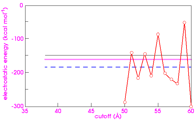
Figure 17 shows the electrostatic energy for quartz as computed by various techniques. One would feel that all the techniques should converge to the same value at high cutoff distances. However, the direct atom-based cutoffs approach yields results that fluctuate wildly as the cutoff increases, even for rather large cutoffs. The problem is that the sum is only conditionally convergent. As the cutoff increases, charges of opposite sign are taken into account and the partial sum is modified significantly. Worse, reordering the terms of a conditionally convergent series can yield arbitrary results. The problem then is to find physically and chemically meaningful orderings of the series.
The cell-based (Cell-based cutoffs) and group-based (Charge groups and group-based cutoffs) cutoff techniques are natural candidates. However, they yield somewhat different values (Figure 17), due to the different cutoff conventions employed. The group-based technique computes the result for a sphere, but the cell-based technique computes the result for a parallelepiped that preserves the shape of the unit cell.
A standard Ewald calculation that does not take the dipole moment of the unit cell into account yields yet another value. An Ewald calculation that includes the effect of the dipole moment agrees with the group-based calculation (Figure 17).
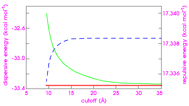
For van der Waals energy, the energy sum is absolutely convergent, and no chaotic behavior arises from the direct approach. Even so, as Figure 18 indicates, the convergence of the dispersive energy is slower than might be expected. Even with a cutoff distance of 30 Å, the error is a significant fraction of 0.1 kcal mol-1. (The Ewald calculation is less costly for comparable accuracy.) The repulsive energy, on the other hand, converges at a cutoff distance of only 15 Å and needs no special treatment. (Atom-based calculations for much larger systems, however, show that sometimes even the repulsive energy can exhibit a surprisingly high error at a cutoff of 12 Å.)
Theory of Ewald technique
For full details on the Ewald summation method and parameter optimization procedure used in MSI's simulation engines, please refer to Karasawa and Goddard (1989).
Eq. 55
 by a convergence function (r), which decreases rapidly with r. Of course, to preserve equality, one must then add a term equal to the product of 1 - (r) with the lattice sum:
Eq. 56
Here, the first term converges quickly, because m(r) decreases rapidly. Ewald's insight was that the second term can be Fourier transformed to provide a rapidly converging sum over the reciprocal lattice. The sum over L in Eq. 56 runs over all lattice vectors, but the i = j terms must be omitted when L = 0.
The convergence functions are, for the electrostatic energy:
Eq. 57
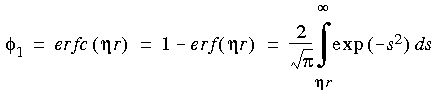 and for the dispersive energy:
Eq. 58
 Optimizing computational effort
The electrostatic convergence function
1 was also used by Catlow and Norgett (1976) and Karasawa and Goddard (1989). The dispersive convergence function 6 was recommended and used by Karasawa and Goddard. The convergence parameter  plays a similar role in both cases. As increases, the real-space sum converges more rapidly and the reciprocal space sum converges more slowly. (That is, a large implies a heavy computational load for reciprocal space, and a small implies a heavy computational load for real space.) Cutoffs must be adjusted accordingly, and processing time is affected by the cutoffs. A value of that balances processing in the real and reciprocal spaces proves to be optimal. The same value of can be used for both the dispersive and electrostatic energy, and thus they can be combined for greater efficiency.
The Discover program automatically chooses
so as to balance the computational loads for real and reciprocal space.
Cerius2·OFF instead uses the inverse of
as input, that is, the ratio of the time required for a real-space calculation to the time for a reciprocal-space calculation. The value chosen for the time ratio does not affect the accuracy of the calculation, only the time taken to perform it. Real-space calculations typically take longer than reciprocal ones, so the value of the time ratio is usually greater than 1.
The Ewald expression for the electrostatic energy is (dropping a factor of 1/4
 0):
0):
Eq. 59
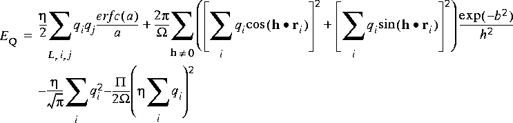
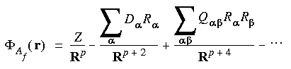
where a = |ri - rj - RL|; ri = Hsi; h = 2(HT)-1n (reciprocal lattice vectors);  = det(H) = cell volume; and b = h \xda 2.
![]() ) holds. The third term in Eq. 59 arises from the self-energy of the charge distributions produced by the introduction of the convergence function. The final term of Eq. 59 is zero if the unit cell is charge neutral, which is normally the case. Indeed, the electrostatic energy in an infinite system of non-neutral cells is formally infinite. However, some applications can involve the use of non-neutral cells. For example, Cation Locator adds cations to the system one by one, and neutrality is not achieved until the final cation is added. The effect of the final term in the equation is to give convergence to a finite value of the energy, which corresponds to a system where the excess charge is neutralized by a compensating uniform background charge density.
) holds. The third term in Eq. 59 arises from the self-energy of the charge distributions produced by the introduction of the convergence function. The final term of Eq. 59 is zero if the unit cell is charge neutral, which is normally the case. Indeed, the electrostatic energy in an infinite system of non-neutral cells is formally infinite. However, some applications can involve the use of non-neutral cells. For example, Cation Locator adds cations to the system one by one, and neutrality is not achieved until the final cation is added. The effect of the final term in the equation is to give convergence to a finite value of the energy, which corresponds to a system where the excess charge is neutralized by a compensating uniform background charge density.
The Ewald sum as it appears in Eq. 59, with no h = 0 term, strictly represents an infinite crystal. A real macroscopic but finite crystal also includes surface contributions, which can be substantial (Deem et al. 1990) and which depend on the dipole moment of the unit cell and the shape of the crystal. However, in a real environment, physical effects such as surface reconstruction and dielectric effects in the surrounding medium serve, in general, to diminish the surface charge. The Cerius2·OFF and CDiscover programs therefore omit such terms, corresponding to the so-called "tin-foil" boundary conditions.
Accuracy of Ewald calculations
You choose the accuracy before beginning calculation
The Ewald method allows you to select, before running the calculation, a level of accuracy for the calculation. (Estimation of the cutoff and convergence constants is difficult, so a facility to automatically calculate these parameters to a certain accuracy (Karasawa & Goddard 1989) is provided instead.)
Ewald processing time grows as N1.5, where N is the number of atoms in the unit cell. Increases in accuracy do not require unreasonable increases in the Ewald lattice cutoff. For acetic acid, for example, increasing the accuracy by 2 orders of magnitude (from 1 e-2 to 1 e-4), with constant repulsive cutoff, increased processing time only about 1.5 fold (from 22.08 to 35.34 seconds) and increased the Ewald lattice cutoff less than 20% (from 11.7 to 13.4 Å).
Although the default Ewald accuracy is acceptable for most single-point energy calculations, tighter accuracy may be required for some minimization and dynamics runs, to assure acceptable gradient accuracy. A value as low as 0.00025 may be preferable if your minimization run fails to converge or your dynamics run misbehaves.
Due to the nature of the Ewald sum method, specific nonbond interaction energies cannot be calculated. When this method is used, the per-atom energy is calculated by using the Ewald sum method, and the nonbond interaction energy is calculated using the group-based method. You can specify cutoffs for the group-based method of nonbond analysis. A large cutoff in the group-based method may give reasonably accurate energies compared with the Ewald sum method.
Ewald sum for models with 2D periodicity
Only for Coulombic terms
If the model has 2D periodicity, an Ewald sum may be applied to the Coulombic terms, using the method of F. Harris (communication). A non-Ewald method must be used for the van der Waals terms in this case, and a large cutoff may be required to obtain good accuracy.
The method is similar in principle to the 3D Ewald sum, but more complex in that one direction must be treated nonperiodically. To avoid loss of accuracy, no cutoff is applied in the nonperiodic direction. However, the method can still be optimized, since fewer terms are required in the periodic sums for those atom pairs having a large separation in the nonperiodic direction. Although the method is slower than a non-Ewald method (or a 3D Ewald sum), it provides very good accuracy.