
| Cerius2 Builders |
Surface models are required for calculations with some modules, for example, the C2·LEED/RHEED module. For calculations using other modules, you can convert surface structures into large nonperiodic superstructures to represent the surface.
The C2·Surface Builder module also helps to visualize surfaces within crystal models that were built with the C2·Crystal Builder module.
This chapter contains information on:
The C2·Surface Builder builds surfaces in which a basic surface unit is repeated using a 2D periodic cell. Many similarities exist between the Crystal Builder module, which builds 3D structures, and the Surface Builder module, which builds 2D structures.
You can also use the surface builder to convert surfaces into superstructures and superlattices.
Any surface can be unbuilt, converting the surface to one cell of a nonperiodic model. All unit cell information is lost.
General procedure
You can build surfaces in two basic ways:
The MSI and CSSR file formats are the only formats that save 2D models, that is, they include the 2D unit cell information. However, once the surface has been converted into a nonperiodic superstructure, any of the file formats used for nonperiodic models can be used to save the structure.
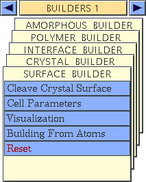
Controls belonging to the C2·Surface Builder module are contained on the SURFACE BUILDER card, which is located by default on the BUILDERS 1 deck of cards. To access the SURFACE BUILDER card, click its name to bring it to the front of the deck of cards, which should now look like this:
Cleaving a surface from a crystal
In building a surface from a 3D crystal, a slab is defined within the crystal and then the slab is cleaved out as a surface.
Build (see Building and unbuilding crystals) or load a crystal model to serve as the starting structure. This model must be loaded into the current Cerius2 session, but need not be the current model.
Select the Cleave Crystal Surface menu item on the SURFACE BUILDER card to open the Cleave Crystal Surface control panel.
Choose the desired crystal model from the model pulldown near the top of the Cleave Crystal Surface control panel. This assures that the surface is cut from the correct crystal.
Enter the Miller indices for the slab in the Direction entry box.
Please see the on-screen help for additional information about the controls in all the panels mentioned here.
Building a surface from a nonperiodic model
Building a surface from a nonperiodic model involves positioning the model within a surface cell and then generating the surface. The model must be built or read in before the cell is defined.
Load or build a nonperiodic model. See Cerius2 Modeling Environment for information on building, saving, and loading models.
Select the Building From Atoms menu item on the SURFACE BUILDER card to open the Building From Atoms control panel.
In the Surface Build Preferences control panel, set the Visualization style to ORIGINAL.
Specifying the unit surface cell
Enter the dimensions of the surface cell in the u, v, and
![]() entry boxes of the Surface Cell Parameters control panel. (The choice of coordinate system has no effect until after the surface is built.) However, choosing an unsuitable 2D cell may lead to many atoms' overlapping and, consequently, many bonds across cell boundaries.
entry boxes of the Surface Cell Parameters control panel. (The choice of coordinate system has no effect until after the surface is built.) However, choosing an unsuitable 2D cell may lead to many atoms' overlapping and, consequently, many bonds across cell boundaries.
Click the BUILD SURFACE pushbutton in the Building From Atoms control panel. The surface cell appears in the model window.
| Operations such as moving atoms can leave the display inconsistent with the visualization style. Checking the Enable automated recalculation box enables automatic recalculation of the display. |
Please see the on-screen help for additional information about the controls in all the panels mentioned here.
Building a surface by adding atoms
Building a surface from individually placed atoms involves positioning them within a surface cell and then generating the surface. The cell is generated before the atoms are placed in it.
Begin with an empty model space.
Select the Building From Atoms menu item on the SURFACE BUILDER card to open the Building From Atoms control panel.
Enter the dimensions of the surface cell in the u, v, and
![]() entry boxes of the Surface Cell Parameters control panel. (The choice of coordinate system has no effect until after the surface is built.)
entry boxes of the Surface Cell Parameters control panel. (The choice of coordinate system has no effect until after the surface is built.)
Click the BUILD SURFACE pushbutton in the Building From Atoms control panel. The surface cell appears in the model window.
Choose the surface fractional (UVd) or Cartesian (XYZ) coordinate system from the popup in the Add Atom control panel.
Please see the on-screen help for additional information about the controls in all the panels mentioned here. For additional information about the Add Atom control panel, see the discussion of build operations in Cerius2 Modeling Environment.
Changing surface lattice vectors
Once a surface is built, you may want to edit the lengths and angles of the surface cell vectors, U and V. This is done through the Surface Cell Parameters control panel. All changes made on this control panel are instantly reflected in the model window.
The effect of lattice alteration on atom position depends on the coordinate type you want to fix:
Open the Surface Cell Parameters control panel by selecting the Cell Parameters menu item from the SURFACE BUILDER card or by clicking the Cell Parameters... pushbutton on the Building From Atoms control panel.
Make the surface model that you want to edit be current.
![]() entry boxes and/or the sliders to enter new dimensions for the U and V surface vectors and for the angle
entry boxes and/or the sliders to enter new dimensions for the U and V surface vectors and for the angle ![]() between the vectors.
between the vectors.
Please see the on-screen help for additional information about the controls in all the panels mentioned here.
Creating a surface superstructure
Once a block of surface cells is displayed in the current model space, you may want to convert this display into a surface superlattice model or into a nonperiodic superstructure model. For example:
Open the Surface Visualization control panel by clicking the Visualization menu item on the SURFACE BUILDER card. Alternatively, click the Visualization... menu item on the Building From Atoms control panel.
Use the Surface Cell Display Range controls in the Surface Visualization control panel to display the number of surface cells that you want included in the superstructure or superlattice.
To create one large periodic surface structure (a superlattice) from the displayed atoms, click the Periodic Superlattice action button in the Cleave Crystal Surface or Building From Atoms control panel.
Please see the on-screen help for additional information about the controls in all the panels mentioned here.
Unbuilding a surface
Accessing the tools
Open the Building From Atoms control panel by selecting the Building From Atoms menu item on the SURFACE BUILDER card.
To return the model to its nonperiodic asymmetric unit, deleting all symmetry copies of atoms and the surface cell, click the UNBUILD SURFACE pushbutton to return the surface model to a nonperiodic model.
Please see the on-screen help for additional information about the controls in all the panels mentioned here.
It is often easier to visualize the current surface by displaying a large block of surface cells instead of just one.![]()
Displaying surfaces
Open the Surface Visualization control panel by selecting the Visualization menu item from the SURFACE BUILDER card. Alternatively, click the Visualization... pushbutton on the Building From Atoms control panel.
Enter the number of surface cells to be displayed along the U and V directions.