B
Quantum 1 Module Utilities

Quantum mechanics applications often use Z-matrix internal coordinate representation rather than standard Cartesian coordinates to describe models. For Quantum 1 applications that require it, Cerius2 automatically generates a Z-matrix description of the model that is to be studied.
Most Quantum 1 applications provide Z-matrix manipulation functionality that allows you to alter the structure of an existing model by editing its Z-matrix. They also provide tools for changing between Cartesian and Z-matrix representations and for adding dummy atoms.
This chapter explains
- Editing Z-matrices
- Adding dummy atoms to a model

Editing Z-matrices
Z-matrix format is a method of representing model structures using internal coordinates. A Z-matrix representation of a structure specifies the locations of atoms and the bonds between them in terms of distances, angles, and dihedral (torsion) angles.
Cerius2 Z-matrix format
Each atom in a model is described on a separate line in the Z-matrix definition. The number of entries on each line varies, depending on how many atoms are in the model and what other atoms have already been defined (see Figure 1). For example, a bond length cannot be specified until two atoms are defined; a bond angle cannot be specified until three atoms are defined.
The following sections describe the makeup of the lines that form a Cerius2 Z-matrix.
Line 1
Because the Z-matrix is an internal representation in which each atom is described relative to others in the structure, the first line simply defines an arbitrarily chosen atom that serves as the conceptual origin of the matrix. Only two entries appear on the first line: the line number and the atom name.
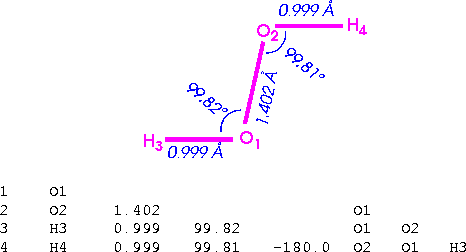
For example, in the hydrogen peroxide model shown above, where oxygen atom assigned serial number one is chosen as the first reference atom, line one is:
1 O1
Atom labels
Z-matrix atom labels are made up of the atomic symbol and the atom serial number assigned by Cerius2 (for example, C1, H4, and so on). To display Cerius2 atom serial numbers for your model, select NUMBERS from the atom labeling popup on the Visualizer's main control panel.
Line 2
The second line in the matrix defines the position of a second atom relative to that of the atom defined on the first line. The distance between these atoms can now be defined. Four entries appear on the line. These specify the line number (2), the label of the second atom, the bond length, and the label of the atom it is bonded to (the first atom), in that order.
(In fact, these atoms need not be actually bonded to each other if, for example, an atom being defined is a dummy atom or a metal ion. However, it is easier to describe a Z-matrix as if all the atoms are bonded as a single molecule.)
For example, in the hydrogen peroxide model shown in Figure 1, where the other oxygen atom, O2, is bonded to O1 by a bond of length 1.402 Å and is chosen as the reference atom for the second line, line 2 is:
2 O2 1.402 O1
Line 3
The third line in the matrix defines the position of a third atom relative to the two previously defined atoms. The angle formed between the two bonds described can now be defined. Six entries appear on the line. These specify the line number (3), the label of the third atom, the distance between the third atom and the atom to which it is bonded, the bond angle formed, the label of the atom to which the atom is bonded, and the label of the last atom that describes the defined bond angle.
For example, in the hydrogen peroxide model shown in Figure 1, where the hydrogen atom, H3, is bonded to O1 by a bond of length 0.999 Å, forming a bond angle of 99.82° between itself, O1, and O2, and is chosen as the reference atom for the third line, line 3 is:
3 H3 0.999 99.82 O1 O2
Lines 4 onward
Starting at line 4, the positions of all subsequent atoms (each of which is, of course, bonded to one of the previously defined atoms) can be defined completely. A torsion angle (which describes the angle between the plane formed by the first, second, and third atoms and the plane formed by the second, third, and fourth atoms) can be defined on the fourth and all subsequent lines. Eight entries appear on complete lines. These describe (not in order):
For example, in the hydrogen peroxide model shown in Figure 1, only one more atom, the hydrogen atom (H4) exists and, consequently, only one torsion and one complete line can be defined. H4 is connected to O2 by a bond of length 0.999 Å, forming a bond angle of 99.81° between itself, O2, and O1, and a torsion angle of -180° between itself, O2, O1, and H3. The fourth and final line is:
4 H4 0.999 99.81 -180 O2 O1 H3
Z-Matrix Editor control panel
Controlling geometry via the Z-matrix
The Z-Matrix Editor control panel (accessed by selecting the Geometry/Z-Matrix menu item in many Quantum 1 cards) contains controls that allow you to construct, view, and edit Z-matrices. Using the Z-Matrix Editor, you can automatically generate or manually construct a Z-matrix for the current model. Once the Z-matrix is fully constructed (or if one exists already), you can view the matrix, examine the Z-matrix connectivity of your model, and alter the model's geometry by altering the bond lengths, angles, and torsions that define the matrix.
The Z-Matrix Editor also provides access to a utility that allows you to change between Cartesian and Z-matrix representations of atoms in the model.
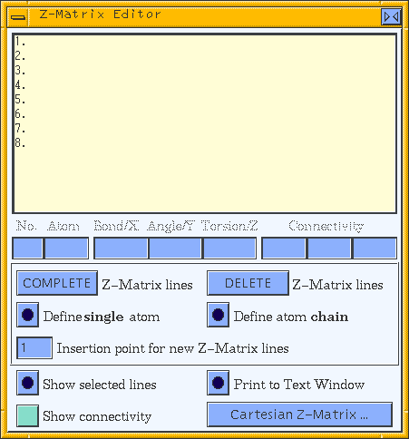
The Z-Matrix Editor control panel may look something like this when you first open it:
:

Caution
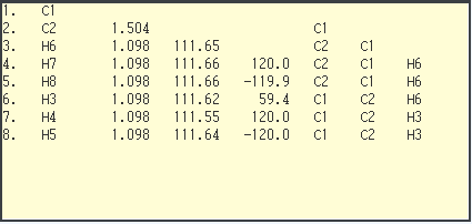
The Z-matrix list box displays the Z-matrix for the current model. If nothing but a list of numbers appears here (as shown above), click the COMPLETE Z-Matrix lines pushbutton to generate the Z-matrix for your model. The list box should now look something like:

You can select one or more lines from the Z-matrix list for editing, using the usual mouse selection mechanism (please see Cerius2 Modeling Environment if you are not yet familiar with selecting items in list boxes).
Using the editor
You can edit the bond, angle, and torsion values of selected lines in the Z-matrix by entering values in the boxes below the Z-matrix list box.
Use the Z-matrix specifiers (entry boxes that correspond to the column titles shown in the Z-matrix format summary table under Z-matrix format summary) to specify new values for the lines selected from the Z-matrix list.
These controls include several which function similarly:
- For all these controls, you can select and edit multiple lines using the same representation; lines using different representations cannot be edited together.
The Define single atom action button defines a new (or redefines an existing) Z-matrix entry for an atom selected from the model. To create a new definition (at the line specified by the Insertion point for new Z-Matrix lines entry box), select the atom for which the Z-matrix entry is to be defined. You should then select, in order, other atoms corresponding to the connectivity atoms that define the bond, bond angle, and torsion that make up the entry to be defined. Therefore, for an atom (or atoms) that is to be defined on:
When all the necessary atoms are selected, click the Define single atom action button.
To redefine an existing entry in the Z-matrix, you can select the reference atom and connectivity atoms used to define it from the model in the same way that you would to define a new entry and click the Define single atom action button. Alternatively, select the line in the Z-matrix list, click the Show selected lines action button to highlight the atoms in the model, and then click the Define single atom action button.
Use the Define atom chain action button to add a new chain definition to the Z-matrix. The defined chain appears in the order in which it was selected in the model (that is, the first-selected atom forms the first line, the second-selected atom forms the second line, and so on).
Please see the on-screen help for information on all the controls in this control panel.
Cartesian vs. Z-matrix representations
The Cerius2 Z-Matrix editor supports the specification and editing of model structures in a format that combines Cartesian coordinates and Z-matrix specifications. Such mixed representations can be useful for specifying models for which some parts are more easily specified in Cartesian coordinates and others more easily described in Z-matrix format. Controls on the Cartesian Z-Matrix control panel allow you to change entries in the Z-Matrix Editor control panel's Z-matrix list freely between the two representations.
Cartesian Z-Matrix control panel
The Cartesian Z-Matrix control panel (accessed by clicking the Cartesian Z-Matrix... pushbutton on the Z-Matrix Editor control panel) contains controls that allow you to add selected atoms to the Z-matrix list in Cartesian notation and change selected lines in the list between Z-matrix and Cartesian representation.
Please see the on-screen help for information about the controls in this control panel.

Adding dummy atoms to a model
What dummy atoms are used for
Dummy atoms, which appear in Cerius2 models with the label X, are often added to models to make the specification of constraints or Z-matrix atom definitions easier. Dummy atoms are also often essential for defining constraints that are awkward or impossible to define with only real atoms. Constraints are used to ensure that variable values remain within certain defined limits during the course of calculations.
The Quantum 1 interfaces offer three tools (available on the Dummy Atoms control panel) that provide you the flexibility of adding dummy atoms using Cartesian coordinates or Z-matrix positions or according to their relative positions with respect to atoms selected in the model.
Dummy Atoms control panel
To access the Dummy Atoms control panel, select the Geometry/Dummy Atoms menu item on most Quantum 1 cards.
Creating dummy atoms
You can define dummy atoms by defining their coordinates yourself:
- To create a dummy atom at a particular location in Cartesian space, set the x, y, z coordinates in the upper entry box and click the Add atom at (x,y,x) action button.
- To create a dummy atom at a point relative to the positions of other atoms (i.e., defined by internal coordinates), first select three atoms (see Cerius2 Modeling Environment for how to select more than one atom), enter the desired coordinates in the middle entry box, and click the Add atom at (
 ,
, ,
, ) action button, where
  = distance,
  = angle, and
  = dihedral angle.
You can also create a dummy atom at an automatically calculated point relative to those of atoms in your model:
- To create a dummy atom positioned at the geometrical average of the coordinates of any two or more atoms, select those atoms in your model, assure that MID-POINT is chosen in the popup at the bottom of the Dummy Atoms control panel, and click the associated Add atom at action button.
- To create a dummy atom positioned at the internal or external bisector (i.e., along the line bisecting the angle defined by three atoms), select three atoms in your model, select INTERNAL BISECTOR or EXTERNAL BISECTOR, respectively, from the popup, and click the associated Add atom at action button. The three atoms do not need to be bonded to one another.
- To create a dummy atom positioned along the perpendicular to the line joining two atoms or to the best-fit plane through three or more atoms, select two or more atoms in your model, select PERPENDICULAR from the popup, and click the associated Add atom at action button.
Recovering from errors
You can always correct errors by selecting the dummy atom and then selecting the Edit/Cut menu item from the main Visualizer control panel.

Last updated December 06, 1998 at 11:51AM Pacific Standard Time.
Copyright © 1998, Molecular Simulations, Inc. All rights
reserved.


![]()
