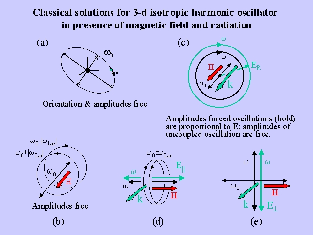
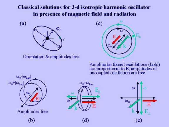
Solutions for a 3-dimensional isotropic harmonic oscillator in the presence of a stationary magnetic field and an oscillating electric radiation field.
List of Contents

Unperturbed oscillator

The equation of motion of a particle in a central isotropic harmonic potential is given by

                                                                             (1)
where r is the 3-d position vector of the particle, m is its mass, and k the force constant of the force that drives the particle back to the center (see Figure). The equation of motion can be written as
                                                                          (2a)

                                                                               (2b)

The equation has a 3-fold degenerate set of eigen vibrations with angular frequency w0. The equation is linear and any superposition of solutions is again a solution. For a given initial velocity (v) the particle (green dot) under influence of the central force (centered at black dot) moves in the plane defined by the force center and the velocity vector and describes an ellipse around the force center (Figure (a)). The motion can be decomposed into two orthogonal linear vibrations (Figure (a)), which have a phase difference of p/2 and independent amplitudes (indicated by double arrows). Thus, orientation and amplitudes of the orbit of the unperturbed oscillator can be chosen freely, but the frequency of revolution is fixed.

List of Contents

Effect of a magnetic field: the Zeeman effect

In the presence of a magnetic field (H) the motions of a charged particle (with charge e) perpendicular to the field are subject to Lorentz forces. Introducing this force into Eq 1 yields

                                                                 (3)
(e can here be either positive or negative). The Cartesian components of this vector equation are given by
                                                                     (4a)

                                                                  (4b)

                                                                            (4c)

The Cartesian coordinates (x, y, z) refer to a right-handed coordinate frame (this convention is essential for a proper assignment of the rotational sense associated with the periodic time factor). The last equation can be solved independently from the former two and yields
                                                                                (5)
The former two equations for the real amplitudes x and y can be combined into a single equation for the complex amplitude
r+ = x+iy                                                                                   (6)

                                                                 (7)

The original equations are recovered from Eq 7 by taking the real and the imaginary part. The stationary solutions are of the form
                                                                               (8)
Substitution yields for w the relation
                                                             (9)
which has two solutions (Figure (b))
                                                                    (10)
The corresponding solutions for the orbits describe right (+) and left (-) circular motions that are oriented normal to the field with angular frequencies with magnitudes
                                                                    (11a)

                                                                    (11b)

                                                                           (12)

The latter quantity is called the Larmor angular frequency which is proportional the the field strength. For an electron (e < 0) wLar < 0, thus wL > wR. There is also a linear eigen vibration parallel to the magnetic field (Figure (b)) with unperturbed frequency w0 of the free oscillator (Eq 4c). The degeneracy of the eigen vibrations is completely removed in the presence of a magnetic field. The splitting of energy levels is called the Zeeman effect, after its discoverer Pieter Zeeman (1897). The equation of motion is linear thus, as in the case for H = 0, any superposition of eigen vibrations is a solution of the dynamical problem. Combinations of the circular motions give rise to rosette type of orbits, as a result of the frequency difference caused by H. In classical electrodynamics, a charged particle (here, an electron) radiates when being in accelerated motion. Spectral analysis of the resulting radiation yields lines at the three eigen frequencies of the electronic vibrations.

The oscillator emits radiation in all directions. The light emitted by oscillator with angular frequency w0+|wLar| and propagating in the direction of the field (towards the reader of Figure (b, c)) is left circularly polarized. The light emitted by the same oscillator in the direction opposite to the field (away from the reader) is right circularly polarized. Accordingly, the polarizations for w0-|wLar| are obtained by interchanging left and right in the previous sentence. Thus, in writing wR and wL we refer to the sense of rotation observed by looking at the system into direction –H (This definition of left and right is not based on the wave vector k, see Figure (b))

List of Contents

Non-resonant interaction with radiation incident parallel to the applied magnetic field: the Faraday effect also called Magnetic Circular Birefringence

In the presence of an electric field the equation of motion of the electron reads

                                                         (13)
Equation 13 is nonlinear due to the presence of the electric field term EX (X labels the polarization) and the solutions are not anymore superimposable. In the case of a monochromatic (frequency w) beam of circularly polarized light incident parallel to the magnetic field (X = Left or Right), there is for each polarization a unique solution for the electronic motion in the plane perpendicular to the magnetic field (the particular solution of the inhomogeneous differential equation). We consider here the non-resonance case in which the light frequency w differs from the electronic eigen frequency w0: w¹w0. The Cartesian components of Eq 13 are given by
                                                     (14a)

                                                   (14b)

                                                                                                                (14c)
By adding i times the second equation to the first equation we obtain
                                                                     (15)
In a right-handed coordinate frame, w > 0 corresponds to right circular and w < 0 to left circular. The periodic solutions for Eq 15 have the form
                                                                                     (16)
The electron executes a forced periodic motion with a frequency equal to that of the rotating electric field of the incident radiation. Substitution into Eq 15 yields the relation
                                                                         (17)
Solving for R gives the amplitude of the electronic motion induced by the radiation field
                                                                                         (18)
The amplitude R is proportional to the strength of the radiation field, E0. For w > 0, we find
                                                                                          (19)
and for w < 0
                                                                                        (20)
The H-dependent term in the denominator introduces a dependence of the electronic orbit on the rotational sense of the radiation field. (The radii are negative for e < 0. This reflects the fact that the displacement of the electron is opposite to the direction of the electric field.) In the case that w < w0 and taking into account that e < 0, it follows that |RR| > |RL|. In other words, light that is right circular polarized with respect to the field enhances the magnitude of the electronic polarization (Figure (c)). Analogously, light that is left circular polarized with respect to the field diminishes the magnitude of the electronic polarization. The difference leads to magneto optical activity (see below). As in the case for the free oscillator, the equation for the electronic motion parallel to H is linear and independent of both H and E. This mode can therefore be ignored.

Let us now consider a material containing a macroscopic number of oscillators (N per unit of volume). The electronic displacements induced by circularly polarized light give rise to the electric polarization field

                                                                             (21)
As we are dealing with visible light, the wavelength is large on the molecular scale. Thus, in good approximation it can be assumed that E is position independent over the dimensions of an oscillator. As a consequence, the direction of incidence of the light wave (i.e., the k vector) is irrelevant for the present consideration. Thus, as it was noted above, the only thing that matters here is the rotational sense of the electric radiation field with respect to the magnetic field in the forward direction of time. Accordingly, we have considered E above as a function of time but not of the spatial coordinates. Based on wavelength considerations, the propagation of light in the visible range can be described by means of macroscopic fields. Using elementary Maxwell theory, the polarization (P) is related to the electric field (E) by a factor depending on the refractive index, n:
                                                                 (22a)
Similarly, the electric polarization of the medium by a polarized light component (labelled X) can be written as
                                                           (22b)
As the time-dependent factor is the same for all fields (P, E, D), it cancels. Substitution of the expressions for RX in Eqs 21 and 22b and division by E0 yields the expressions
                                             (23a)
and
                                             (23b)
from which the refractive indices for right and left circularly polarized light can be inferred. The refractive indices depend on the light frequency (w), the magnetic field (H), and the density of oscillators (N). In zero field where nR = nL = n, one obtains the dispersion relation n = n(w). In nonzero field, the dispersion relations for L and R are slightly different, due to the presence of the H-dependent term in the denominator. The propagation speeds of L and R circularly polarized light through the material are given by cR = c/nR and cL = c/nL, respectively, where c is the light speed in vacuum. As the refractive indices differ, the corresponding light velocities differ as well. This difference leads to an effect called birefringence or double refraction. As its origin is magnetic, it is referred to as Magnetic Circular Birefringence (or, after its discoverer, the Faraday effect). If one makes the approximation that
                                                                                  (24)
the difference of the refractive indices for left and right circularly polarized light can be expressed as
                                             (25)
The expression gives a measure for the rotation of plane polarized light by the magnetized material. The rotation angle is linear in the field and proportional to the number of oscillators the beam encounters per unit of surface (N). In addition, the rotation increases linearly with the distance (l) covered by the radiation. The rotation can be expressed as
                                                                              (26)
The quantity vMCB is called the Verdet constant,
                                                            (27)
The sign of the rotation does not change when w crosses w0. In the general case, this expression is to be summed over different values for w0 to account for systems with more than one electronic transition.

In summary, MCB results from a difference in the electric polarization of the medium by L and R circularly polarized light, which originates from the Zeeman splitting of the electronic energies. The following inequalities hold: wR < wL, PR > PL, nR > nL, cR < cL, irrespective of whether w is smaller or greater than w0. L and R are here defined as follows: left is an anti clockwise rotation of plane polarized light and right a clockwise rotation when H points to the observer.

List of Contents

Non-resonant interaction with radiation incident normal to the applied magnetic field: Magnetic Linear Birefringence

Let us consider a beam of monochromatic (frequency w) linearly polarized light incident on electronic oscillators of the type described above, assuming non-resonant conditions, w¹w0. As in the case of the MCB, the electrons in stationary orbits that are coupled to the radiation field perform forced motions. Since the electronic system is cylindrically symmetric along an axis parallel to the magnetic field (H), all polarization planes of light propagating parallel to H are equivalent, precluding any birefringence to occur for symmetry reasons. The situation changes if the light is incident on the oscillator in a direction perpendicular to H (Figure (d, e)). The equation of electronic motion has the same form as in Eq 13,

                                                        (28)
but now the electric radiation field is plane polarized parallel (X = || ) or perpendicular (X = ^ ) to the magnetic field (Figure (d, e)). For parallel polarization, the electrons in the circular orbits perpendicular H do not couple to the electric radiation field (E), and for perpendicular polarization, the linear electronic oscillation parallel to H does not couple to E. These modes can further be ignored as they do not affect the radiation field. Determination of the electronic oscillations that couple to E requires a more subtle analysis. The simplest case is found for E|| where the electric radiation field is coupled to electrons performing a linear oscillation parallel to H (Figure (d)). This oscillation is not affected by H and does not give rise to any magneto-optical effect. In the case of E^ the electronic motion is elliptic due to the interplay of the electric forces driving the electron up and down and the Lorentz forces which alternately pull the electron back and forth (Figure (e)). The latter motions, however, are small when wLar << w0w, a condition which is fulfilled apart from a narrow frequency range around the resonance frequency. Consequently, the electronic motion enforced by E^ is practically linear (Figure (e)) despite the presence of the magnetic field. In addition to the ellipticity, there is also a change in the amplitude of the electronic motion perpendicular to the magnetic field, which is quadratic in the field strength, H. The magnetic field effect on the refractive index n^ can be evaluated from the solutions of Eq 28 in an analogous manner as it was shown for MCB in the previous section. We present here only the result for the field-induced change in n^ relative to the field-independent index n||:
                                         (29)
Upon traversing the medium, the difference in the refractive indices gives rise to an increasing degree of ellipticity in a linearly polarized light beam of which the polarization plane does not coincide with the directions parallel and perpendicular to the field (i.e., a polarization not coinciding with an eigen vector). This effect is called Linear Birefringence or Linear Double Refraction, and as its origin is magnetic, it is referred to as Magnetic Linear Birefringence. The ellipticity angle, aMLB, obtained for light with a polarization plane bisecting the angle between the H and its normal (i.e., a plane with an inclination of 45° relative to H) is given by
                                                                     (30)
l is the path length covered by the beam in the material. The quantity vMLB expresses the dependence of the ellipticity angle on electronic resonance frequency (w0), radiation frequency (w), oscillator density (N), refractive index (n), and fundamental constants (e, m, c),
                                                 (31)
The electronic MLB discussed here is an intrisic electronic effect and differs principally from the magnetic linear birefringence associated with alignment of molecular chromophores in a magnetic field studied by Cotton and Mouton. Contrary to the Verdet constant (for MCB), vMLB flips sign if w crosses w0. For w < w0, n|| < n^ from which follows that the parallel mode is the faster component at the "red side" of the transition (w0). The sense of rotation in the resulting elliptically polarized radiation is that of the field (H) toward the polarization plane of the incident radiation over the smallest angle (here 45° ). To our knowledge, Eq 31 has thus far not been subjected to experimental test. In the general case, however, the expression is to be summed over different values for w0 to account for systems with more than one electronic transition, leading to complexities that will undoubtedly hamper the observation of such an effect.

List of Contents

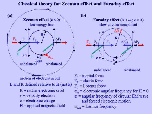
Zeeman effect and Faraday effect: A vector analysis

The effects due to Zeeman (Figure (a)) and Faraday (Figure (b)) can be interpreted in terms of simple vector diagrams which depict the electronic orbits and the three forces involved: the inertial force (FI), the elastic force (FE) and the Lorentz force (FL). As we consider only stationary circular solutions for the electronic motion,

                                                                                    (32)
the time-dependent factor can be eliminated from the equation of motion and the forces represented by their magnitudes
                                                                        (33a)

                                                               (33b)

                                                      (33c)

The three forces are directed along the radius of the electronic motion. A positive sign indicates an inward force and a minus sign an outward force. The forces indicated in Figure (a, b) are for the right circular motion, which belongs to the low energy line of the Zeeman spectrum. The equation of motion can now be expressed as
                                                                     (34)
and further simplified by passing to accelerations
                                                             (35)


Substitution of Eqs 33 yields

                                                         (36)
(which is identical to Eq 9). For H = 0, the angular frequency w of the electronic motion is w0 and the FI and FE are of equal magnitude but opposite sign (see Figure, left). For H ¹ 0, there arises an outward Lorentz force. The only way to compensate FL is by increasing the value of FI (FE can only be changed by changing "spring dilatation" R but, as we have argued above, this factor drops from the equation of motion). Rebalancing is effected by a decrease in the angular frequency,
                                                                       (37)
The inertial force becomes
                                                         (38)
where we have ignored a small term on the order H2. It follows that FI is changed by the amount
                                                                          (39)
indicated in Figure (a) (right side of circle). Thus, by slowing down the electronic motion there results a negative increment in the inertial force, balancing the Lorentz (Figure (a)):
                                                                          (40)
 In the case of the Faraday effect, the frequency of the electronic motion is equal to the frequency of the driving force, which is thus a fixed quantity that cannot be used for balancing FL. For H = 0, the radius of the electronic orbit is (Figure (b))
                                                                    (41)
(The value R < 0 obtained for e < 0 reflects a displacement of the electron opposite to the direction of the electric field. The minus sign is essential if we take the ratio of P and E in deriving the expression for n2-1, but does not affect the diagram given in the Figure where the magnitude of the radius is indicated.) The Lorentz force arising in this situation is associated with the velocity (v = R w, R of Eq 41) of a particle that orbits with frequency w of the forced electronic motion at radius R (see Eq 33c),
                                                        (42)
A change DRR in the radius alters both the inertial and elastic forces by the increments
                                                                       (43)
and
                                                                       (44)
indicated in the Figure. These forces balance the Lorentz force if the following identity holds (Figure (b) left)
                                                                (45)
DR can be solved from Eq 45,
                                                    (46)
DRR is a negative increment of the negative radius R and corresponds to a positive increment in the modulus |RR|. An analogously derivation for left circular polarized light results in a decrease in the modulus of the radius (DRL = -DRR > 0), hence |RR| > |RL|. The difference of the radii for the forced electronic motions is
                                 (47)
From this expression, the difference of the refractive indices for left and right circular polarized light can be obtained in a way analogous to that described in a previous section, i.e., by multiplication with
                                                                                    (48)
This yields the expression
                                                  (49)
which is identical to the expression Eq 25 given above.

List of Contents