Optical activity
List of Contents
Light interacts with matter.
The interaction leads to an array of phenomena of which the most common
are refraction (also called refringence) and reflection.
These phenomena depend on the type of matter (e.g., metal or dielectric)
and the properties of the light, such as color (= frequency), direction
of propagation with respect to the material, and polarization. Any form
of polarization dependence of the interaction between light and matter
is called optical activity. This definition includes effects that
occur without the presence of an applied magnetic or electric field (so-called
natural
optical activity) and polarization-dependent phenomena that occur upon
placing matter in a magnetic or electric field (so-called magneto-
and electro-optical activity). Two types of optical activity can
be discerned: birefringence (also called double refraction)
and dichroism. We define birefringence as the dependence
of the speed of monochromatic light on polarization. Circular
birefringence (CB) occurs when the speeds of left and right circular
polarized light differ and linear birefringence (LB) when the speeds
of two orthogonal linearly polarized light beams differ. CB is the most
common phenomenon and gives rise to a rotation of the polarization plane
of linearly polarized light (see below). In the case that these phenomena
are caused under the influence of an applied magnetic field they are called
magnetic
circular birefringence (MCB) and magnetic linear birefringence
(MLB). We define dichroism as the dependence of the absorption
(or emission) of monochromatic light on polarization. Circular dichroism
(CD) occurs when the absorptions (or emissions) of left and rightcircularly
polarized light in matter differ and linear dichroism (LD) when
the absorptions (emissions) of two orthogonal linearly polarized
light beams differ. In the case that these phenomena are caused under the
influence of an applied magnetic field they are called magnetic circular
dichroism (MCD) and magnetic linear dichroism (MLD).
List of Contents
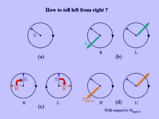
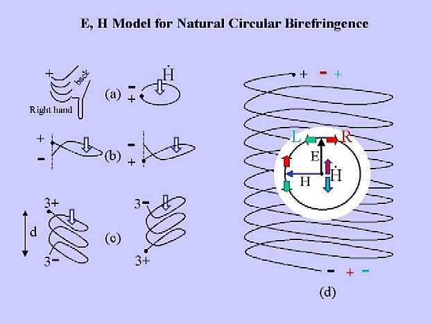
How to tell left from right?
Figure
(a) depicts the time evolution of the oscillating electric field component
of a circularly polarized monochromatic light beam at a fixed position
in space. Can one tell from Figure (a) whether the
light is left or right circularly polarized? The answer is
no, one
cant! To know the sense of rotation, one needs to specify either the
direction
of light propagation (indicated by the k vector in Figure
(b)) or the magnetic component of the electro-magnetic field
(indicated in Figure (c)). From the readers point
of view the sense of rotation of E is the same in all four diagrams in
Figure (b, c). However, if the light propagates
toward
the reader the polarization is right circular (R) and away
from the reader the polarization is left circular (L) (Figure
(b)). If we consider the 90° angle between
H and E in Figure (c) then we see that
H rotates
toward E in the case of right circular polarization and E
rotates toward H in the case left circular polarization. These
characterizations are intrinsic properties of light and independent of
readers perspective. Just like the reader for telling left from right,
a physical system must somehow take into account either the combination
of E and k or of E and H in order to be optically active. In other words,
one can discern two types of physical mechanism for explaining natural
optical activity: E, k mechanisms and E, H mechanisms. The
E, k mechanisms depend essentially on the spatial variation of the electro-magnetic
wave along the direction k and the E, H mechanisms on an interplay of electric
polarization and magnetic induction. A more detailed mechanism for either
one will be specified further on. In the presence of an applied magnetic
(or electric) field one should think of the physical system as "matter
plus field". So defined, the system provides a unique spatial direction
of reference (namely the field) for unambiguously assigning a rotational
sense to the rotating electric field E. The rotational sense defined with
respect to the applied field is indicated by R' or L' in Figure
(d). The sense defined with respect of the field can either coincide
or be opposite to the rotational sense of the radiation (the latter being
defined with respect to k). Magneto-optical effects involving circular
or elliptic radiation depend essentially on the distinction between R'
and L' and not on that between L and R (see below).
List of Contents
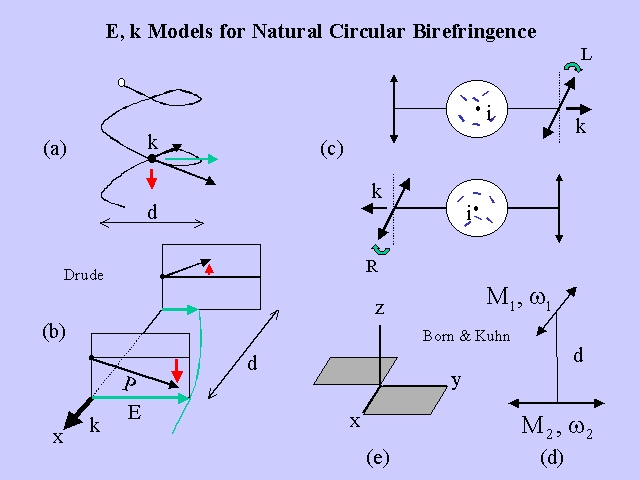
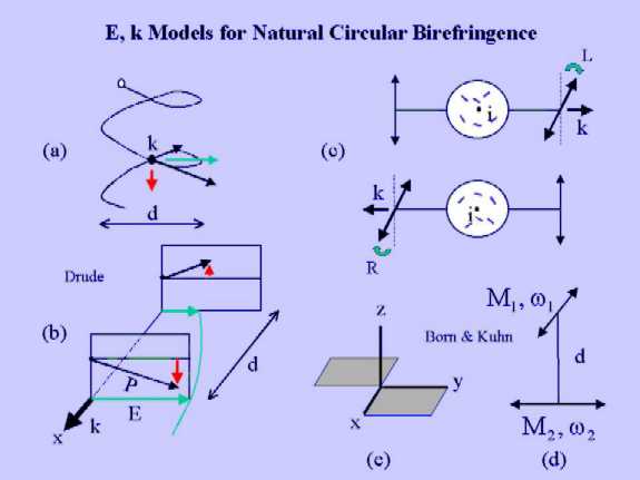
Mechanisms for natural circular
birefringence
E, k models
In 1874 Ludwig Boltzmann
published a paper concerning "the relation between the rotation of the
polarization plane and the wavelength of different colors" in which he
criticized an expression for the dispersion relation given by von Lang
and Stefan. Therein Boltzmann stated: It seems to me probable on
theoretical grounds, that the angle of rotation of the plane of polarization
could be expressed better by a formula of the form
 than by the formula
 .
Boltzmann based his critique on the argument that "The rotation of the
plane of polarization is one of those phenomena which depend on the fact
that the wave lengths are no longer very large compared with the sphere
of action of a molecule". Indeed, the rotation approaches zero in the long
wave length limit according to the expression proposed by Boltzmann. The
discussion is a prelude to the development of E, k models for natural circular
birefringence.
.
Boltzmann based his critique on the argument that "The rotation of the
plane of polarization is one of those phenomena which depend on the fact
that the wave lengths are no longer very large compared with the sphere
of action of a molecule". Indeed, the rotation approaches zero in the long
wave length limit according to the expression proposed by Boltzmann. The
discussion is a prelude to the development of E, k models for natural circular
birefringence.
The first quantitative theory
for natural circular birefringence was formulated by Drude in his "Lehrbuch
der Optik" that was published in 1900. Drude started has analysis by comparing
a chiral molecule with a cylindrical coil with diameter d (Figure
(a, b)). The molecule was assumed to contain a single charged particle
(electron) whose motion was confined to the coil. Subsequently, the system
was placed in a beam of polarized light incident normal to the axis of
the coil (the light propagates toward reader in Figure
(a)), and the interaction of the electric field component of the radiation
field (E in Figure (a, b)) on the charged particle
was analyzed. Although Drudes analysis has been criticized in later work
(see below), it is of interest to follow some of his arguments. A cornerstone
of Drudes theory is that there exists a non-local interaction between
the radiation field and charged particles. Let us assume that the incident
wave is linearly polarized as indicated in Figure (a).
A perspective view of Figure (a) is presented in
Figure
(b). It shows the electric field (green arrows) at two diametrical
points of the coil along the k vector. The electric force acting on the
particle leads to displacements (P) along the coil. The displacements have
two components, one along the E and one perpendicular to E (Figure
(b)). The perpendicular components are due to the spatial configuration
of the coil (see Figure (a)) and have opposite signs
in the planes in the front and the back (Figure (b)).
The fields, however, are slightly different in size due to the spatial
progression of the phase (a section of the electric wave has been indicated
by a green curve in Figure (b)). As a consequence,
the perpendicular forces in the two planes have different magnitudes and
do not cancel. According to the concept of "non-local interaction" the
particle interacts simultaneously with the electric fields at the two diametrical
points and undergoes a net perpendicular displacement, which is the sum
of the displacements in the font and back plane (red arrow in
Figure
(a)). Of course, polarization of a dielectricum perpendicular to the
polarization plane of the incident radiation is required for a rotation
of the polarization plane to occur. For a rotation, however, the perpendicular
displacement should be in phase with the displacement parallel to E. The
perpendicular displacement, however, is proportional to the derivative
of the electric field, that is, 90º out of phase compared to the parallel
displacement. Thus, there arises an elliptical distortion of the wave (CD),
and not a rotation (CB). A complete mathematical analysis of the Drude
model, given by Kuhn (Zeitschrift für physikalische Chemie, 20
(1933) 325), supports the conclusion that this model does not yield
circular birefringence. The theoretical expression for the CB derived by
Drude agrees, however, closely with that given by Kuhn (see below), indicating
that the original treatment does not apply to the physical model given
in Figure (a, b). Born criticized the Drude model
on several grounds. The Drude model is essentially a classical theory in
which matter is built from point like particles. From a classical perspective
the origin of the non-local interactions is obscure. This concept seems
to fit better into a quantum mechanical description of the problem where
one is dealing with spatially delocalized states. The classical description
of matter as an ensemble of elastically bound charged particles has been
successfully applied to the interpretation of a variety of phenomena, including
the dispersion of the refractive index, the Zeeman effect, and the Faraday
effect. Along similar lines, a theory for natural CB has been proposed
by Born (Physikalisch Zeitschift XVI (1915) 251). An ensemble
of harmonic oscillators, however, is optically inactive, even if the oscillators
are anisotropic. This point is illustrated in Figure
(c). The diagram in the upper panel shows a plane polarized light beam
traversing a medium containing harmonic oscillators (small blue sticks).
Suppose there would be a rotation (L). Inversion (i) yields the diagram
in the lower panel of Figure (c). The oscillators
and the rotation from readers point of view are not changed by
the inversion, but the wave vector has flipped its sign. Thus, the intrinsic
sense of the rotation is reversed to R. The upper and lower panel represent,
however, the same physical situation, hence a
= -a and the rotation is zero. To overcome this
difficulty, Born introduced the concept of interacting harmonic
oscillators. Figure (d) shows the simplest realization
of an optically active system based on interacting harmonic oscillators,
proposed by Kuhn. The potential energy is given by
(1)
List of Contents
E, H models
The prototype of an E, H
model was formulated by Rosenfeld (Zeitschrift für Physik 52
(1928) 161). The final result of his lengthy quantum-mechanical
derivation was the following simple expression for
the rotational angle of the polarization plane for a randomly oriented
sample of molecules
(3)
 ,
it follows that L and R rotations (indicated by bold arrows) give rise
to oppositely signed derivatives
,
it follows that L and R rotations (indicated by bold arrows) give rise
to oppositely signed derivatives  .
Accordingly, the induction dipole associated with R circular polarized
light is aligned antiparallel (see charges indicated in red) to the electric-field
induced dipole, leading to a reduction of the charge polarization
along the coil axis. The induction dipole associated with L circular polarized
light is aligned parallel (see charges indicated in blue) to the electric-field
induced dipole, leading to an increase of the charge polarization.
As the refractive index is an increasing function of the polarization,
we obtain nL > nR in the example of Figure
(d). This result implies that cL < cR and
leads to a right rotation (for an observed looking into the beam) of the
polarization plane when the coil in Figure (d) is
traversed by linearly polarized light. Of course, the sign of the rotation
is reversed if the coil is replaced by its mirror image.
.
Accordingly, the induction dipole associated with R circular polarized
light is aligned antiparallel (see charges indicated in red) to the electric-field
induced dipole, leading to a reduction of the charge polarization
along the coil axis. The induction dipole associated with L circular polarized
light is aligned parallel (see charges indicated in blue) to the electric-field
induced dipole, leading to an increase of the charge polarization.
As the refractive index is an increasing function of the polarization,
we obtain nL > nR in the example of Figure
(d). This result implies that cL < cR and
leads to a right rotation (for an observed looking into the beam) of the
polarization plane when the coil in Figure (d) is
traversed by linearly polarized light. Of course, the sign of the rotation
is reversed if the coil is replaced by its mirror image.
Representing a molecule
by a coil, as it was done in the foregoing discussion, may seem unrealistic.
Nonetheless, the example suggests that coupled oscillators are not a condition
sine
qua non for natural CB. Eq 3 has been used by Condon et al. for calculating
the CB of a single particle moving in an anharmonic potential of the form
 .
.
The study demonstrated convincingly that a single electron moving in
a field of suitable dissymmetry can give rise to optical rotatory power
in a medium containing molecules of this type. Eq 3 formulates CB as a
one-electron operator and is therefore ideally suited for calculating rotatory
power from molecular orbital theories. Such applications have been reported
by Kauzmann et al.
List of Contents